Configuring the Inertial Navigation System (INS)
Applicable receivers: AX940i | BD940-INS | BX940 | BD992-INS | BX992
In this topic:
This topic will help with the setup and operation in the field of the Inertial Navigation System (INS) included in the following products: AX940, BD940-INS, BX940, BD992-INS, and BX992 as well as obsolete products such as the BX935 and BD935-INS. This topic typically covers the dual-antenna setup since the single antenna and smart antenna setups are subsets of that.
If these products are used in a mode with the INS feature disabled, follow instructions for GNSS-only usage, such as the OEM GNSS Receiver Setup application note.
1. Tips and tricks for installation and measure-up
We recommend that you also review the INS Setup Training Slides and Measure-up Video to see the complete process that occurs in an INS measure-up.
When mounting the components of the system, especially the hardware containing the IMU, it is important to mount the unit rigidly to the vehicle. Avoid these conditions:
-
Excessive vibration: Avoid mounting locations which are subject to vibration from the engine, transmission, implements (i.e. mower deck), etc.
-
Springboarding: Make certain that the mounting surface is thick enough that it will not flex and is rigidly attached in all directions so that it does not springboard.
-
Mounting that will allow lever arms to change: Make certain that mounting of all components are ridged with respect to each other. Mounting the IMU on a tractor frame and the GNSS antennas on the air-ride cab may cause problems for the INS engine if lever arms change (as the cab rocks) and when dynamics between components are not consistent.
Seek to align the IMU so that its axes are coplanar with the vehicle or reference axes. Misalignments may be corrected but the process is often tedious and troublesome.
With the antenna setup, we always recommend setting the Antenna Type to ensure that satellite measurement biases are modeled and corrected properly for that antenna. For INS setup, we recommend setting the Antenna Measurement Method to the Antenna Phase Center (APC), and setting the Antenna Height to zero.
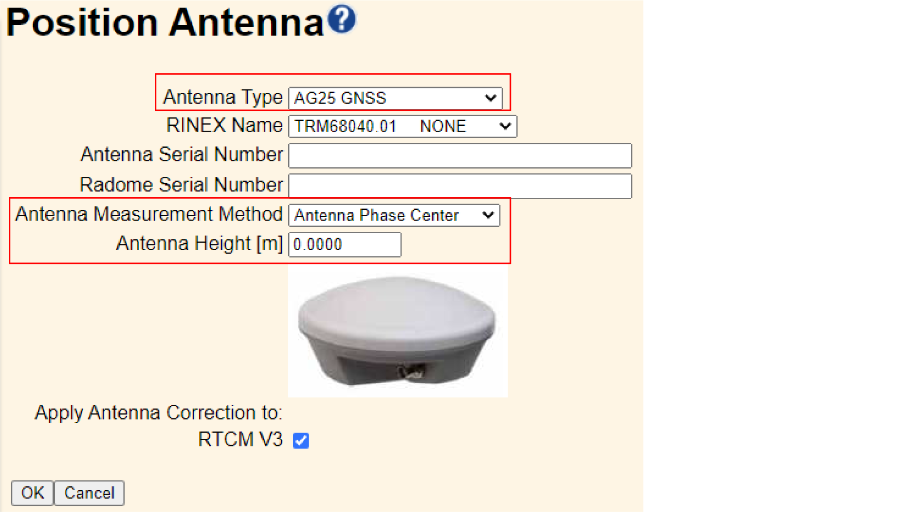
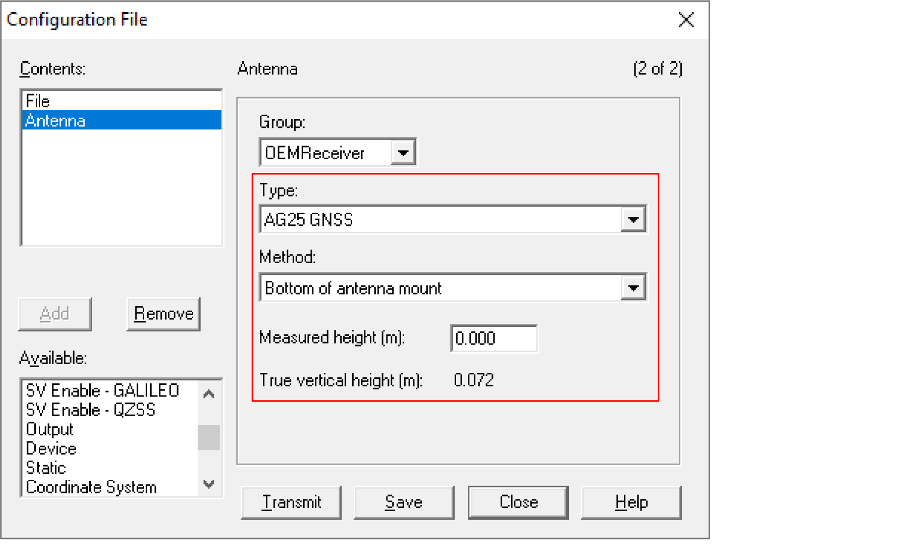
Check the antenna label or use the Configuration Toolbox software to find the “True vertical” height of the APC above the bottom of the antenna mount (since that will likely be the easiest place to measure to). Lever arm measurement should be measured to the APC.
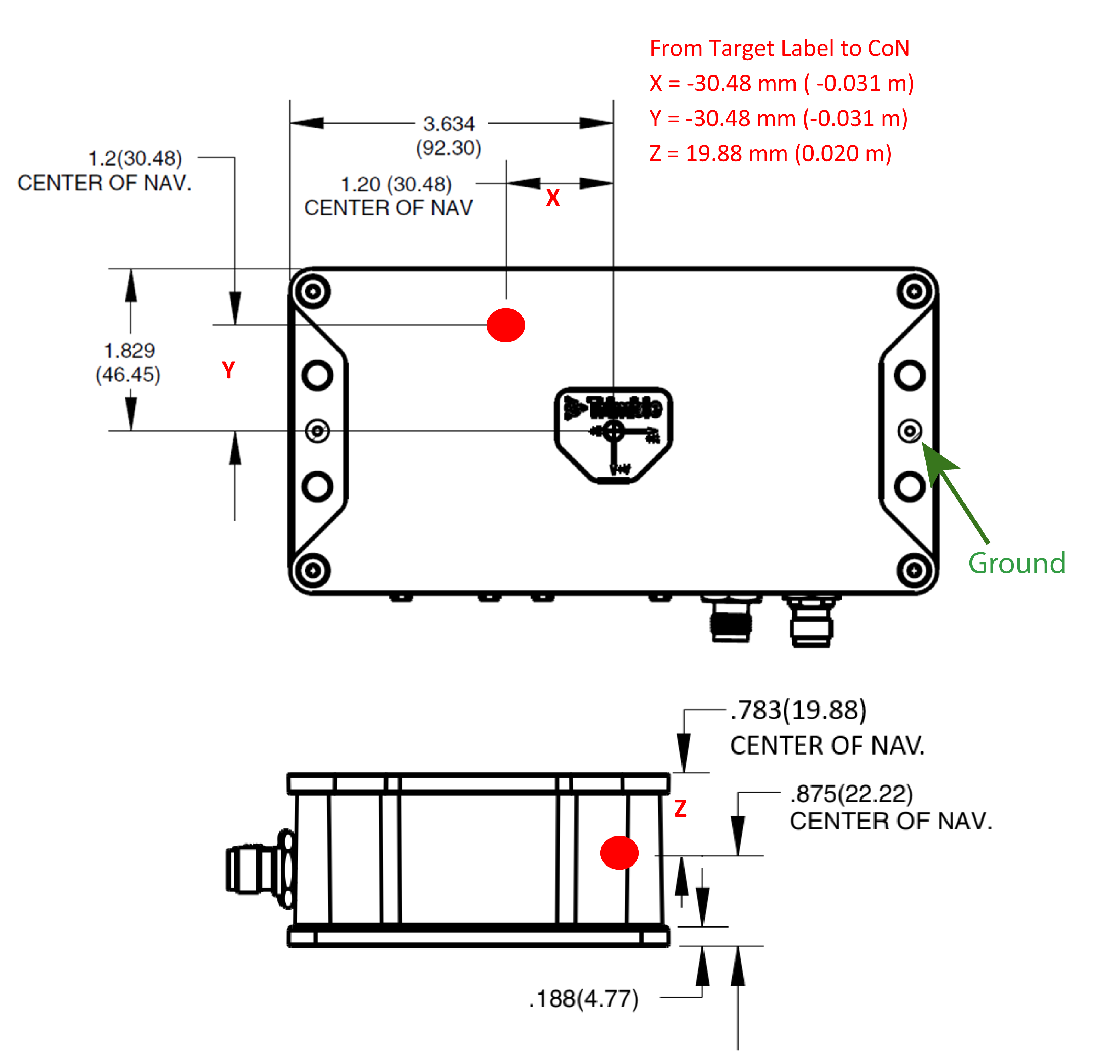
When measuring the Reference to IMU Lever Arm, remember to measure to the center of navigation, which is identified in the manual. This is the sensing location for the IMU components. The following figure shows the center of navigation (CoN) for the BX992 receiver enclosure.
2. Setting up INS using the web interface
Once you know the IP address (DHCP or Static), type this address into a web browser. The following screen appears:
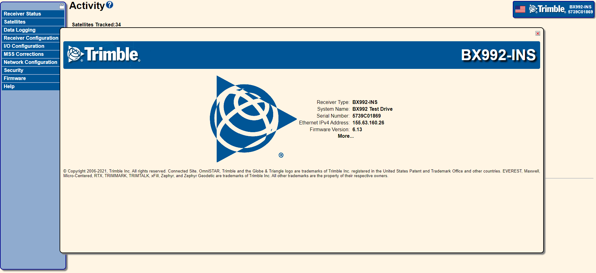
The web interface will help you to enter and visually verify that the INS configuration is correctly setup. Select Receiver Configuration / INS.
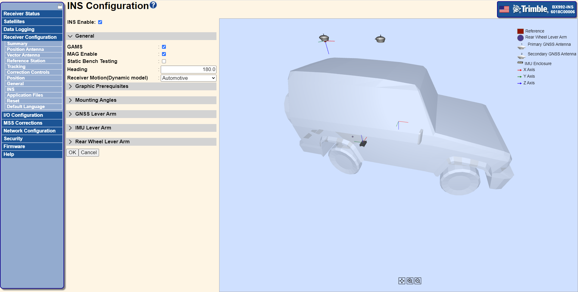
If you want to use DCOL commands to set and query the INS configuration parameters, see INS configuration using D1h commands.
The following sections explain the various parts of the INS configuration:
-
GAMS (if dual-antenna is supported)
-
Graphic Prerequisites to set the model size and to set the location of the reference
-
Coordinate frames and mounting angles
-
-
-
Vehicle to Reference Mounting Angles
-
Reference to IMU Mounting Angles
-
-
-
Reference to Primary GNSS Lever Arm
-
Primary to Secondary GNSS Baseline Vector (if GAMS is enabled)
-
-
-
Reference to IMU Lever Arm
-
-
-
Reference to Rear Wheel Lever Arm (if Automotive or Mapping Vehicle)
-
INS Enable
Select this check box to enable the INS feature, clear the check box to disable the INS feature. If disabled, the receiver operates in GNSS-only mode.
GAMS
For dual-antenna systems such as the BX992 and the BD992-INS, enabling GAMS (GNSS Azimuth Measurement Subsystem) will turn on support for the second antenna. This enables the system to align when it is first turned on and before movement has occurred. If disabled, the receiver operates in single-antenna INS mode. The INS Status page shows the mode and operational details of GAMS.
MAG Enable
Select this check box to enable the MAG feature, clear the check box to disable the Mag feature. The magnetometer may be used by the INS engine to provide a low accuracy heading before the INS has fully aligned. The magnetometer must be calibrated before it will be used. To calibrate the magnetometer for usage, slowly drive the vehicle in a tight circle a minimum of three times. The calibration accounts for magnetic attraction in the surrounding vehicle, thus if the unit is moved to a different vehicle it should be re-calibrated. The INS Status page shows the magnetometer calibration state and the date of the current calibration.
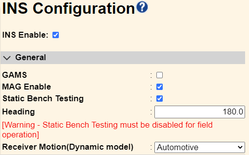
Static Bench Testing and Heading
For field use, ensure that you clear the Static Bench Testing check box. The feature is only useful for bench testing single-antenna systems since it will allow them to align without movement. However, if this check box is left enabled during normal operation it causes position and attitude errors. The Heading setting allows the heading output to be specified when in static bench testing mode; this is only used when in static bench testing.
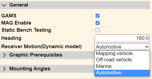
Dynamic Models
The INS comes equipped with a set of dynamic models to best model the application in which the system is being used. The dynamic model sets a number of constraints in the INS engine describing and allowing how this type of vehicle may be allowed to move. The available dynamic models depend on the receivers being used, firmware version, and options available for different part numbers.
Graphic Prerequisites
The Graphic Prerequisites settings enables the 3D model to be set up so that the size of the model and placement of the reference location are consistent with the placement in the real world. However, these settings have no impact on the computed position or attitude.
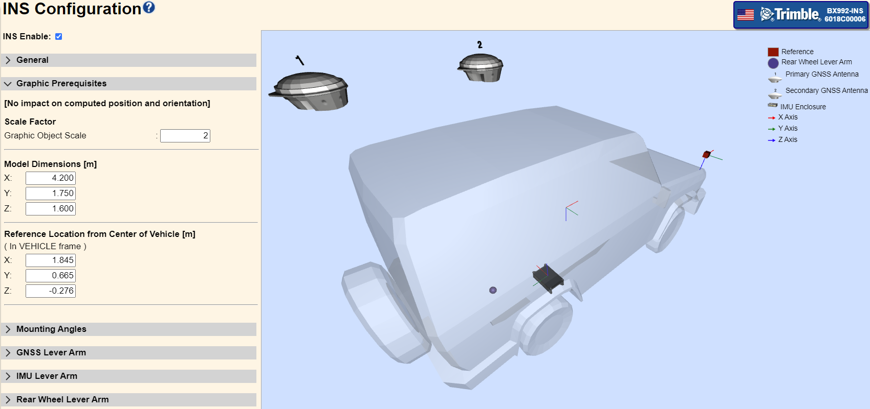
The Scale Factor for the Graphic Object Scale simply adjusts the size of the objects to make them more visible. The Model Dimensions set the size of the vehicle, and the Reference Location from Center of Vehicle sets the placement of the reference. The reference is the point at which the system will output the position solution. Examples of this could be a drill tip or blade near the ground at the front of a vehicle or the focal point of a camera system mounted on the vehicle.
For demonstration purposes, we will place the reference location at the front passenger side of the vehicle’s hood.
Coordinate frames and mounting angles
There are three coordinate frames used during the INS configuration:
-
The vehicle frame is that of the vehicle. See Coordinate frame of the vehicle.
-
The coordinate frame of the reference (a camera in our examples) is that of the reference point or point of interest where the results will be provided. See Coordinate frame of the reference.
-
The IMU coordinate frame is that of the IMU itself. See Coordinate frame of the IMU.
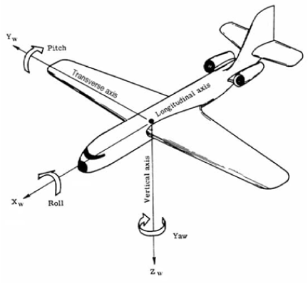
These are all right-handed orthogonal coordinate systems and described in the following sections. The coordinate system was originally applied in aircraft systems, the positive Z-axis facing downward may be counter-intuitive and different than coordinate systems user’s define for their vehicles. Keep in mind that these are simply setup coordinate systems, the output from the system will be positions (latitude, longitude and altitude) and attitude (roll, pitch and yaw/heading). Incorrect setup may affect outputs.
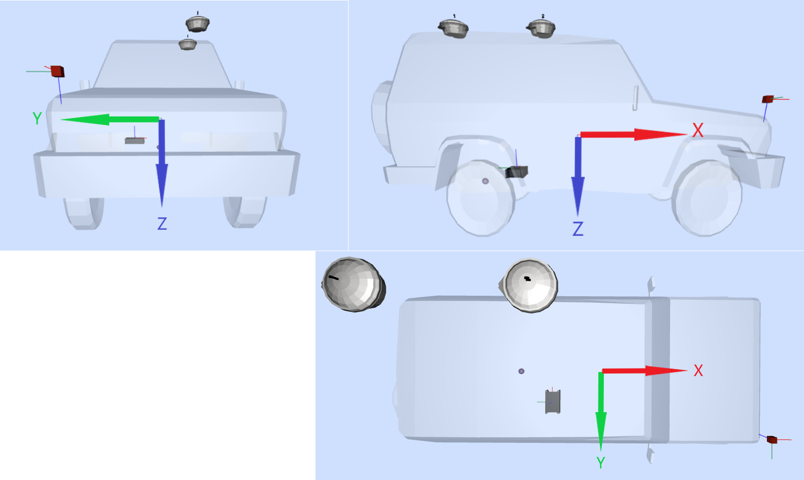
Coordinate frame of the vehicle
The coordinate frame of the vehicle is defined with the +X direction forward in the direction of travel. The +Y direction to the right, and the +Z down (negative Z will point skywards). The following figure illustrates the +X, +Y, and +Z directions.
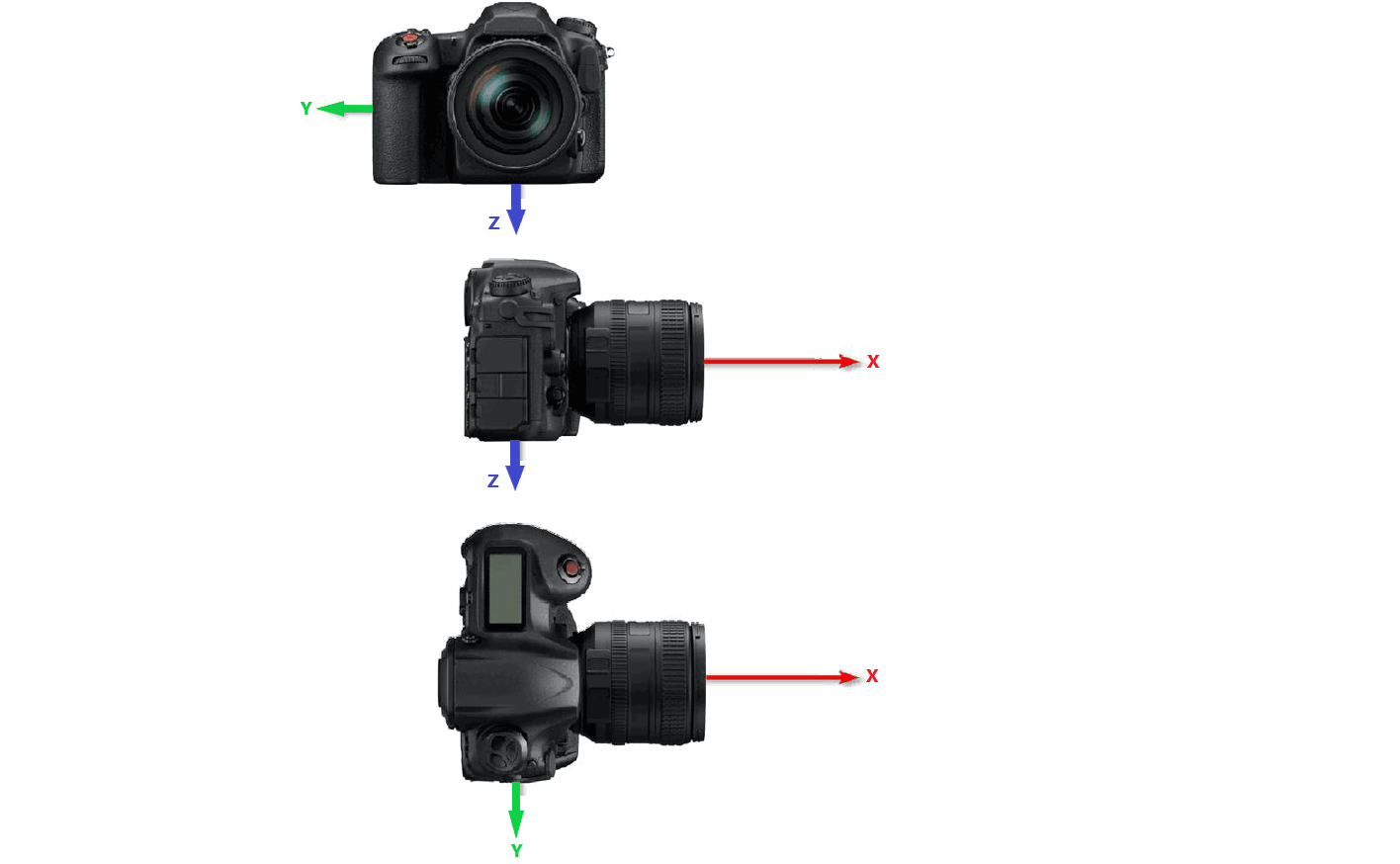
Coordinate frame of the reference
The coordinate frame of the reference defines the system for which attitude will be output. Typically, this is coplanar with the coordinate frame of the vehicle; however, in some instances you may want to set this up to coincide with your coordinate system of interest, such as the optical axis of a camera system. Thus the roll, pitch and yaw/heading will now reflect the camera’s coordinate system. The following figure illustrates the IMU X, Y, and Z axes.
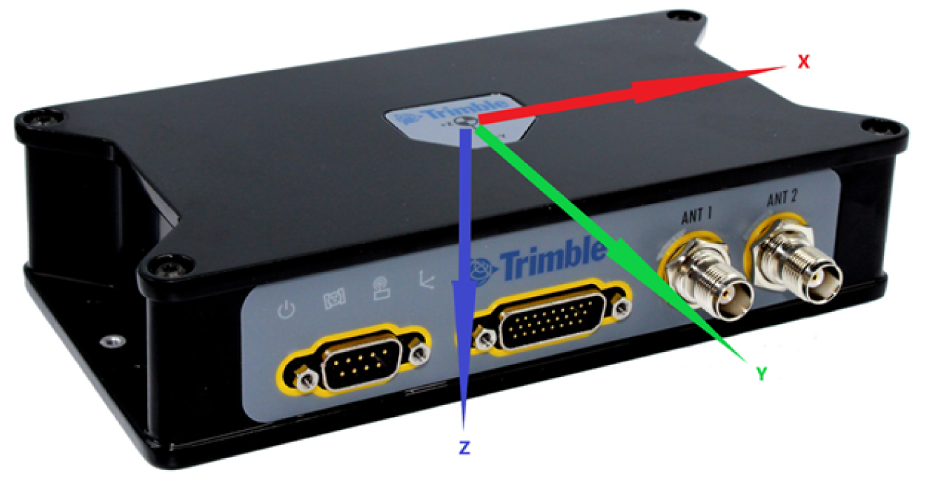
Coordinate frame of the IMU
The coordinate frame of the IMU defines how the accelerometer and gyroscopes are oriented in the hardware (see the manual for each product’s coordinate frame orientation and exact location of the IMU sensing origin). The coordinate frame of the BX940 and BX992 is shown on the label of the unit itself. The following figure illustrates the IMU X, Y, and Z axes of the BX992 receiver enclosure.
Mounting Angles
Vehicle to Reference Mounting Angles
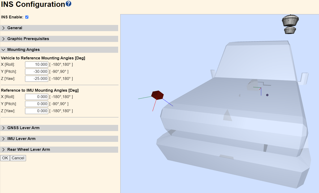
To set the coordinate frame of the reference, use Vehicle to Reference Mounting Angles to specify orientation. The order in which the rotations are applied is: Z-axis, Y-axis, then X-axis.
In the following example, the reference is rotated with respect to the coordinate frame of the vehicle first by -25 degrees about the Z-axis, then by -30 degrees about the Y-axis and finally 10 degrees about the X-axis. Thus, the camera’s optical axis (which coincides with the X-axis) is pointing at the ground in front of the center of the vehicle.
This is a less common operational mode (typically, the coordinate frame of the reference and the vehicle are coplanar) so we will not do any more with this rotated reference example here, but keep in mind that the IMU mounting angles and lever arms are measured in the coordinate frame of the reference.
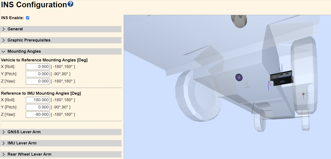
Reference to IMU Mounting Angles
If the coordinate frame of the IMU is not coplanar to the coordinate frame of the reference, the Reference to IMU Mounting Angles will be used to specify how the IMU is oriented. The order in which the rotations are applied is: Z-axis, Y-axis, then X-axis.
NOTE – For the AX940i smart antenna, this will be given as Vehicle to Receiver Mounting Angles, since the IMU is enclosed within the receiver housing. Measurements should be made to the axis label on the surface of the radome at the center, see INS reference location and center of navigation.
In this example, we have returned to coplanar vehicle and reference coordinate systems; however, the IMU is mounted upside down with its connectors to the rear of the vehicle. Thus, a -90 degree Z-axis rotation is applied (so the connectors would face the front of the vehicle), then a 180 degree X-axis rotation is applied (to flip the unit over).
GNSS Lever Arms
Reference to Primary GNSS Lever Arm
The Reference to GNSS Lever Arm is a three-dimensional vector defining the displacement of the GNSS Antenna Phase Center (APC) from Reference Location. It is measured in the vehicle coordinate frame. The 1-σ (sigma) value is your estimate of how accurately the measurements have been made, which is used by the Kalman filter and does impact the final solution and statistical estimates. Try to make these measurements with sub-centimeter accuracy. For best performance, the 1-σ must be 19 mm or less; this will constrain elements of the INS algorithm for optimal performance.
In our example, the vehicle is outfitted with the primary GNSS antenna (1) on the roof at the rear of the vehicle. Our reference location has been set at the front passenger corner of the hood. The X, Y, and Z components are all negative in this layout.
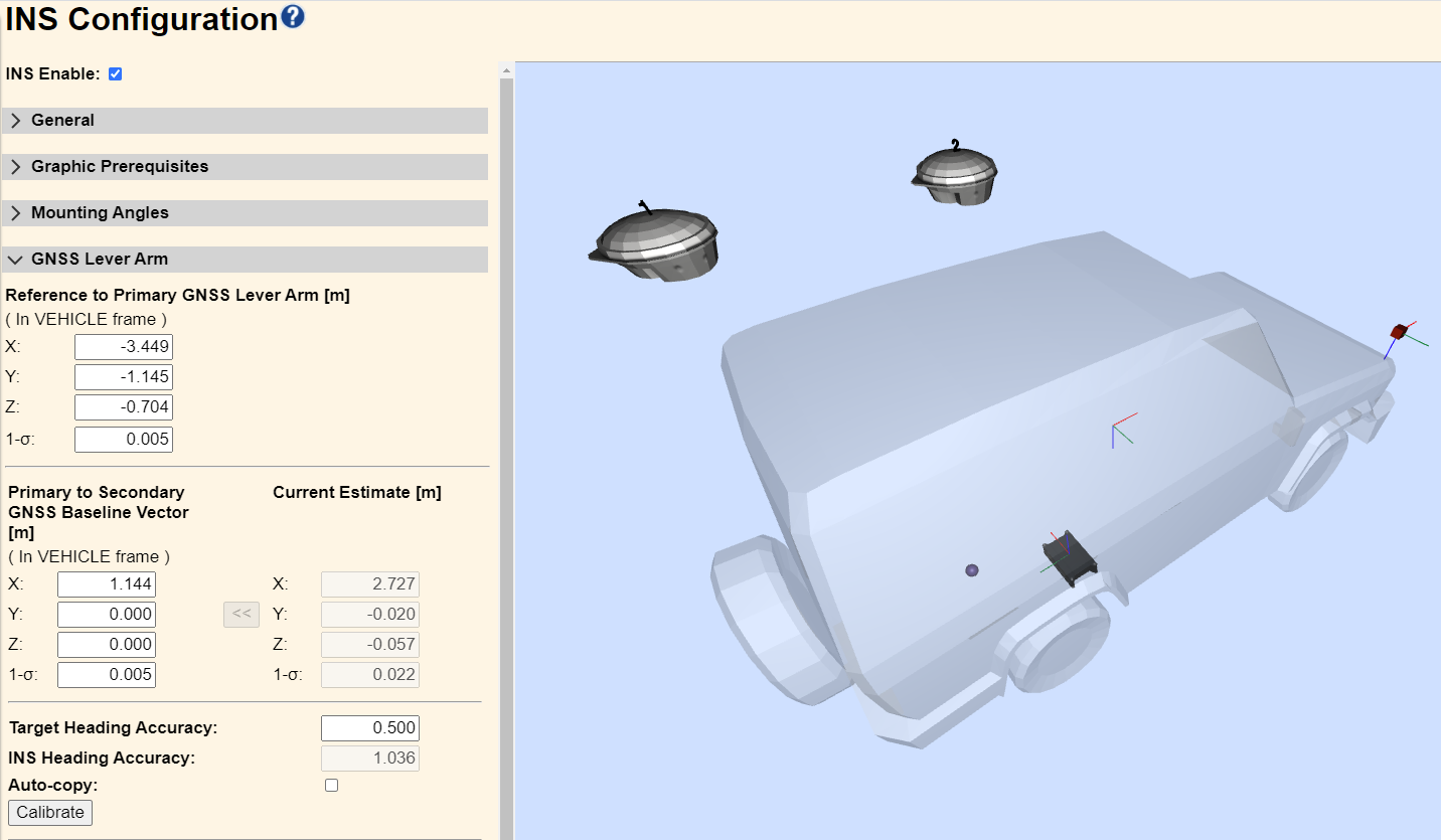
Primary to Secondary GNSS Baseline Vector
For dual-antenna systems with GAMS enabled, the Primary to Secondary GNSS Baseline Vector (lever arm) is a three-dimensional vector defining the displacement of the Secondary GNSS Antenna Phase Center (APC) from the Primary GNSS APC. This displacement is measured in the vehicle body frame. Again, the 1-σ (sigma) value is the user's estimate of how accurately the measurements have been made, and care should be taken to make these measurements with sub-centimeter accuracy. For best performance, the 1-σ must be 4 mm or less; this will constrain elements of the INS algorithm for optimal performance.
In our example shown in the previous figure, the Secondary GNSS APC (2) is directly forward of the Primary GNSS APC (1), thus the X component has been set positive while the Y and Z components are zero.
GAMS calibration
In addition to precisely measuring the lever-arms, the GAMS calibration is also recommended to ensure consistency between the axes of the IMU and the axes in which the lever arms were measured. GAMS calibration is a separate mode within the navigation engine that estimates the baseline vector. Once successful calibration values can be stored. This procedure will not need to be repeated unless the physical location of the antennas is changed.
It is preferable to measure this baseline. If it is not possible to accurately measure the baseline vector and the vehicle is capable of significant dynamic motion, then the GAMS calibration feature can be used. GAMS calibration is a separate mode within the navigation engine that estimates the baseline vector. Once successful calibration values can be stored, this procedure will not need to be repeated, unless the physical location of the antennas is changed.
The GAMS calibration requires data from five or more satellites with a Positional Dilution of Precision (PDOP) of three, or less, to achieve a successful antenna installation calibration. Perform the antenna installation calibration at a time when there is good satellite geometry (i.e. low PDOP), and where unrestricted maneuvering is possible, such as a large, empty, paved parking area.
Before running the GAMS calibration, complete the INS configuration entering all of the mounting angle and lever arm parameters. Check that GAMS is enabled under General. Then in the GNSS Lever Arm (see the previous figure):
-
Enter 0,0,0 for the X,Y,Z Primary to Secondary GNSS Baseline Vector lever arms to allow estimation of the values.
-
Enter a 1-σ value equal to the approximate antenna separation.
-
Enter the required Target Heading Accuracy in degrees. Entries are constrained to the range from 0.01 to 5 degrees. The more accurate the target the better the calibration will be, but smaller heading accuracies are more difficult to achieve. The default is 0.500 degrees.
-
Decide on how to save the calibrated baseline vector. The options are a manual copy or Auto-copy.
-
Manual copy – The copy button (<<) remains greyed out until the INS Heading Accuracy meets the Target Heading Accuracy. Once the button is active, it can be clicked on at any time to save the estimated baseline vector. The copy may be delayed if the dynamics are improving the INS Heading Accuracy beyond what was specified for the Target Heading Accuracy, thereby resulting in a better calibration.
-
Auto-copy – Select to enable auto-copy. When the INS Heading Accuracy meets the Target Heading Accuracy, the calibrated baseline vector values are automatically copied to the installed values and saved.
-
-
Click OK on the INS Configuration page to save the settings.
While the system is stationary (not moving), open the INS Configuration page and the GNSS Lever Arms group.
-
Click Calibrate. This puts the receiver into a specific mode to calibrate the baseline vector.
-
Accelerate the vehicle in a straight line as quickly as possible. For vehicles capable of higher speeds, 60 km/h or faster is recommended. For slower moving platforms, accelerate as quickly as possible to as fast a speed as possible. To achieve suitable precision, more iterations may be required .
-
Once the target speed is reached, apply the vehicle brakes and come to full stop as quickly as possible.
-
Turn the vehicle around and repeat until the INS Heading Accuracy values drop significantly.
NOTE – Ensure there is no GNSS multipath present. It is important that the vehicle accelerations are performed in a straight line.
-
Change the maneuver to perform a number of turns (for example, circular or figure of 8) in an area where there is no GNSS multipath.
-
Monitor the calibration progress in the GNSS Lever Arms window to ensure the INS Heading Accuracy is getting smaller and approaching the Target Heading Accuracy.
-
Go to the next section once the INS Heading Accuracy meets, or exceeds, the Target Heading Accuracy. For optimal performance, it is also recommended that the Current Estimate 1-σ be 4 mm or better.
-
Once the required heading accuracy is achieved, the calibrated baseline vector values are copied to the installation parameters in one of two ways:
-
If Auto-copy was enabled then:
-
The calibrated baseline vector values are automatically copied to the installation parameters.
-
The updated installation parameters are saved.
-
The navigation engine is restarted with the new parameters.
-
The GAMS calibration mode will not be active.
-
-
If Manual copy was used:
-
Once the manual copy button << becomes active:
-
Click << to transfer the estimated baseline vector values to the installation parameters. If the INS Heading Accuracy is still improving with vehicle dynamics, then it is advantageous to wait until the improvement diminishes before copying.
-
Click OK at the bottom of the INS Configuration page to save the settings.
-
Reset the receiver either by power cycle or by a soft reset from the Receiver Configuration / Reset page.
-
-
IMU Lever Arm
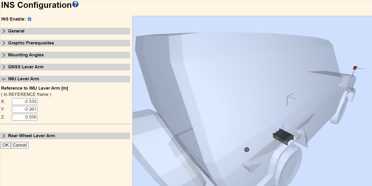
Reference to IMU Lever Arm
The Reference to IMU Lever Arm is a three-dimensional vector defining the displacement of the IMU (at the center of navigation) from the Reference Location. It is measured in the reference coordinate frame. See the following Drawing pages in the Product Guides section for the location and dimensions to the IMU center of navigation.
In our example, the car is outfitted with an INS upside down with the connectors to the rear under the back seat of the vehicle. Our reference location has been set at the front passenger corner of the hood. The X and Y components are negative, but the Z component is positive in this layout. These measurements do not have a measurement quality indicator (1-σ); however, it is desirable to measure this lever arm with sub-centimeter accuracy.
Rear Wheel Lever Arm
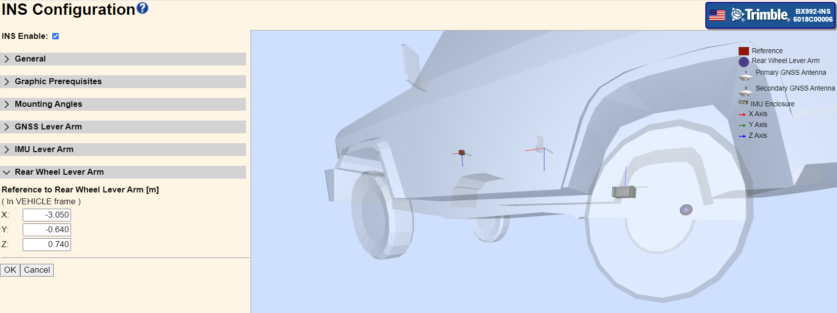
Reference to Rear Wheel Lever Arm
The Reference to Rear Wheel Lever Arm measures the distance (in the vehicle reference frame) X, Y, and Z from the reference to the rear wheels. This is only used if the dynamic model is set to Mapping Vehicle or Automotive. It sets a constraint in the INS engine that models how the rear wheels must follow along as the vehicle turns, thus heading and track angles are the same. The Off-road dynamic model does not have this constraint; it allows for rear wheel slip, thus heading and track angles can differ. The X component is the primary interest since it establishes the line at which the rear wheels pivot, the Y and Z components can be measured to any point on or under the rear wheel axle. These measurements only need to be made with the accuracy of a few centimeters.
3. Verifying GNSS and INS operation
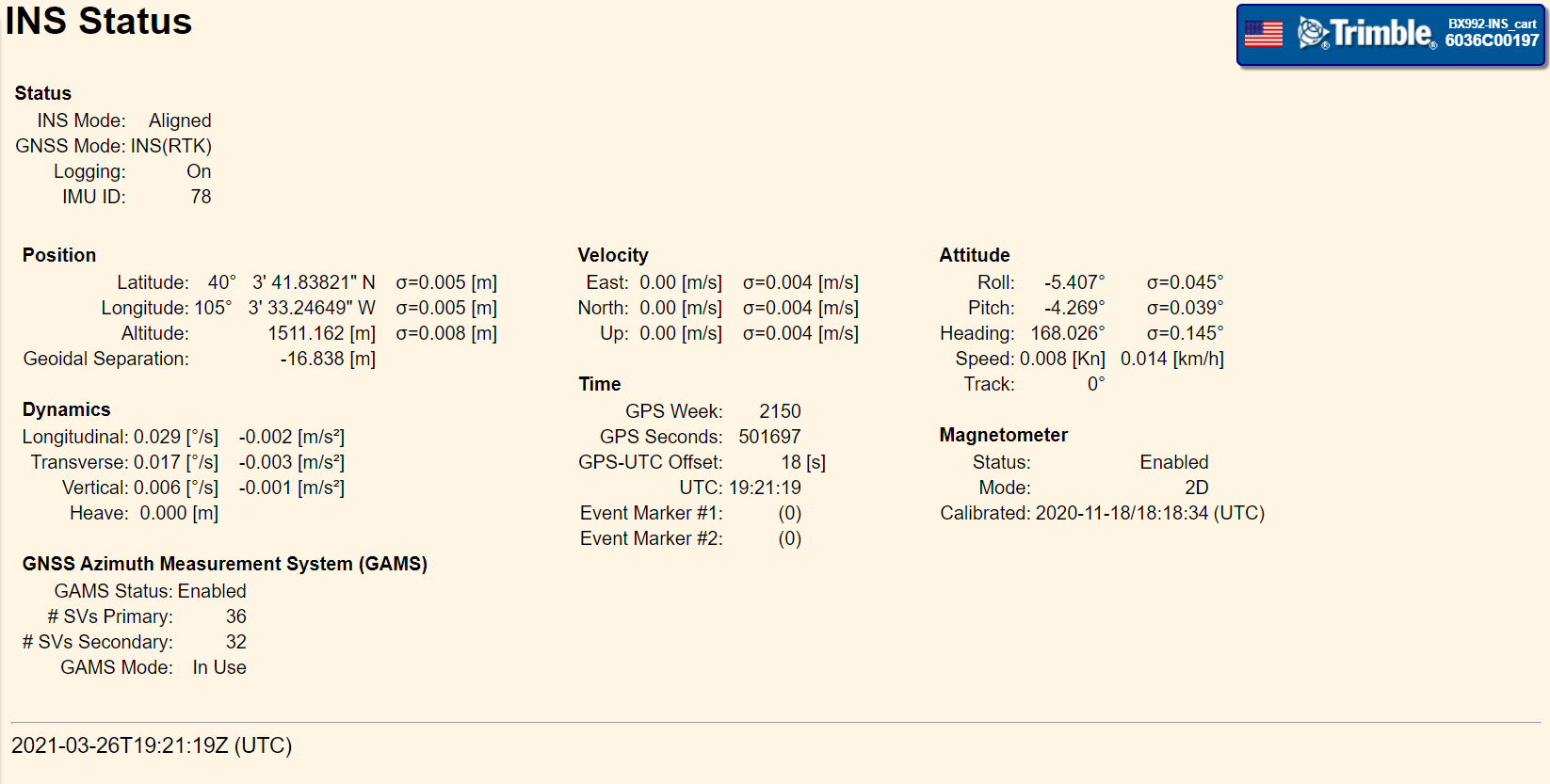
When verifying INS operation, the INS Status page is helpful for assessing INS operation and performance. The page contains information about GNSS and INS mode, positions and sigmas, velocities and sigmas, attitude and sigmas, dynamics, time and event triggers, magnetometer calibration status and GAMS status (if enabled).
Note that when in the Off-Road Vehicle dynamic model when the velocity goes to zero the track angle will read zero.
The dynamics are measured in the coordinate frame of the reference, which in the following figure is the same as the coordinate frame of the vehicle. The following illustration shows roll, pitch and heading/yaw.
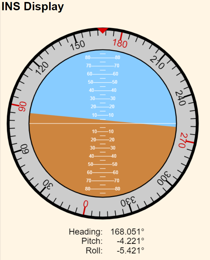
The INS Display page will give an artificial horizon display along with a heading compass:
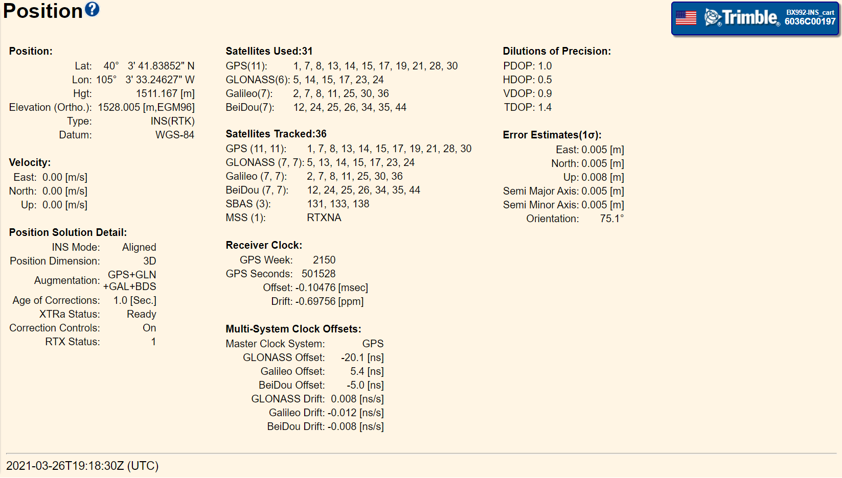
The Position page gives some of the same information, but includes additional information about what satellites are tracked and which satellites are used. Additional information regarding the position solution and that status of xFill/XTRa are also included.
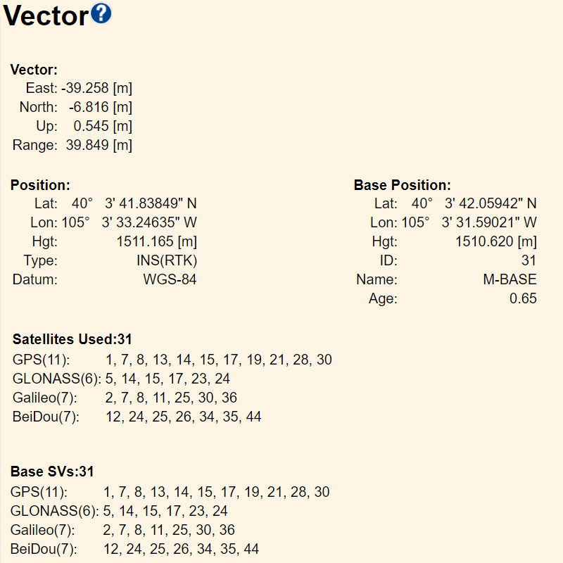
The Vector page gives the RTK vector from the base station to the current rover position, the station information broadcast by the base station and the list of satellites included in the base correction broadcast (which is helpful in verifying the constellations included in the correction broadcast).
4. INS/IMU navigation output
The INS feature can output the INS position and attitude navigation data in NMEA or GSOF formats. Generally, GSOF is preferred because it is a Trimble format specifically designed to output these parameters with the correct precision in a format that is easy for programmers to use.
Recommended GSOF output
For GSOF output information, see GSOF message: Overview.
To obtain INS position and attitude information the GSOF message: INS Full Navigation is recommended. The following record:
31 68 08 66 1D E7 49 E8 03 04 40 44 07 E3 38 76 C6 14 C0 5A 43 CA 82 32 5E 16 40 97 9C A6 10 25 D4 22 BB 27 B6 5C BA DE BB 7E B9 E0 60 B1 3B 49 51 FE C0 15 A2 FE 11 1B FF 77 C0 11 13 60 E0 15 6A C5 40 65 00 D6 4A D6 4E 74 00 00 00 00 00 00 00 00 BD E2 4A 16 BC B9 4A A2 BC 60 33 99 3B A5 BD 11 3C 3C B6 F0 BC 18 82 59
Will contain this information:
RECORD TYPE: 49 (31h (49) INS Full Navigation Info)
RECORD LENGTH: 104
GPS week number: 2150
GPS time (msec): 501697000
IMU alignment status: 3 (3 - Aligned)
GPS quality indicator: 4 (4 - RTK mode with fixed integers)
Latitude (degrees): 40.061621721263
Longitude (degrees): -105.059235142886
Altitude (m): 1511.162
North Velocity (m/s): -0.003
East Velocity (m/s): -0.002
Down Velocity (m/s): -0.000
Total Speed (m/s): 0.003
Roll (degrees): -5.409
Pitch (degrees): -4.269
Heading (degrees): 168.026
Track Angle (degrees): 0.000
Angular rate about longitudinal axis (X) (deg/sec): -0.110
Angular rate about transverse axis (Y) (deg/sec): -0.023
Angular rate about down axis (Z) (deg/sec): -0.014
Longitudinal acceleration (X) (m/s^2): 0.005
Transverse acceleration (Y) (m/s^2): 0.012
Vertical (Down) acceleration (Z) (m/s^2): -0.009
To obtain INS position and attitude error estimation the GSOF message: INS RMS Information is recommended. The following record:
32 2C 08 66 1D E7 49 E8 03 04 3B 99 5D CB 3B AA 60 4F 3C 08 BC 2F 3B 8B 8F 9A 3B 76 84 0D 3B 83 E0 36 3D 39 9A 12 3D 1E 6D C3 3E 14 34 6F
Will contain this information:
RECORD TYPE: 50 (32h (50) INS RMS Info)
RECORD LENGTH: 44
GPS week number: 2150
GPS time (msec): 501697000
IMU alignment status: 3 (3 - Aligned)
GPS quality indicator: 4 (4 - RTK mode with fixed integers)
North Position RMS (m): 0.005
East Position RMS (m): 0.005
Down Position RMS (m): 0.008
North Velocity RMS (m/s): 0.004
East Velocity RMS (m/s): 0.004
Down Velocity RMS (m/s): 0.004
Roll RMS (degrees): 0.045
Pitch RMS (degrees): 0.039
Heading RMS (degrees): 0.145
Recommended NMEA output
For NMEA output information, see NMEA-0183 messages: Overview.
To obtain INS position information the NMEA messages such as GGA or GGK can be used, for example:
$GNGGA,192119.00,4003.69730328,N,10503.55410857,W,4,31,0.5,1528.000,M,-16.838,M,1.0,0031*56
$PTNL,GGK,192119.00,032621,4003.69730328,N,10503.55410857,W,3,31,1.0,EHT1511.162,M*55
For error estimation of the position, the GST message is recommended:
$GNGST,192119.00,0.001,0.005,0.005,77.4,0.005,0.005,0.008*77
To obtain INS attitude, error estimation, and INS alignment state the PASHR – RT300 proprietary roll and pitch sentence is recommended:
$PASHR,192119.000,168.026,T,-5.409,-4.269,,0.045,0.039,0.145,4,3*3B
