Drawings
Applicable receivers: BD940 | BD940-INS
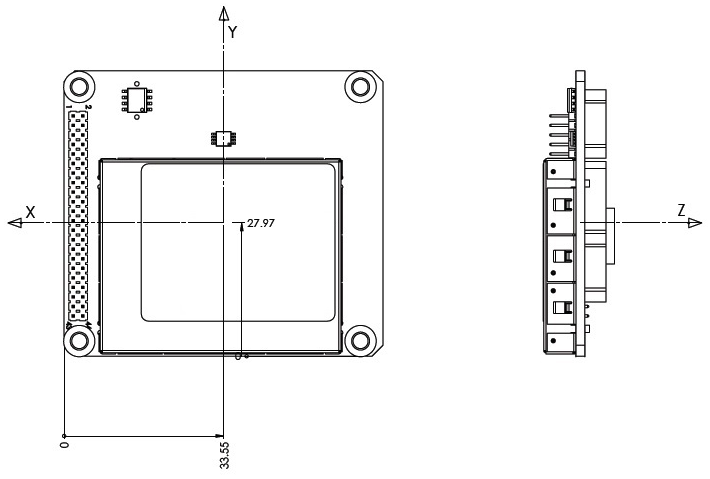
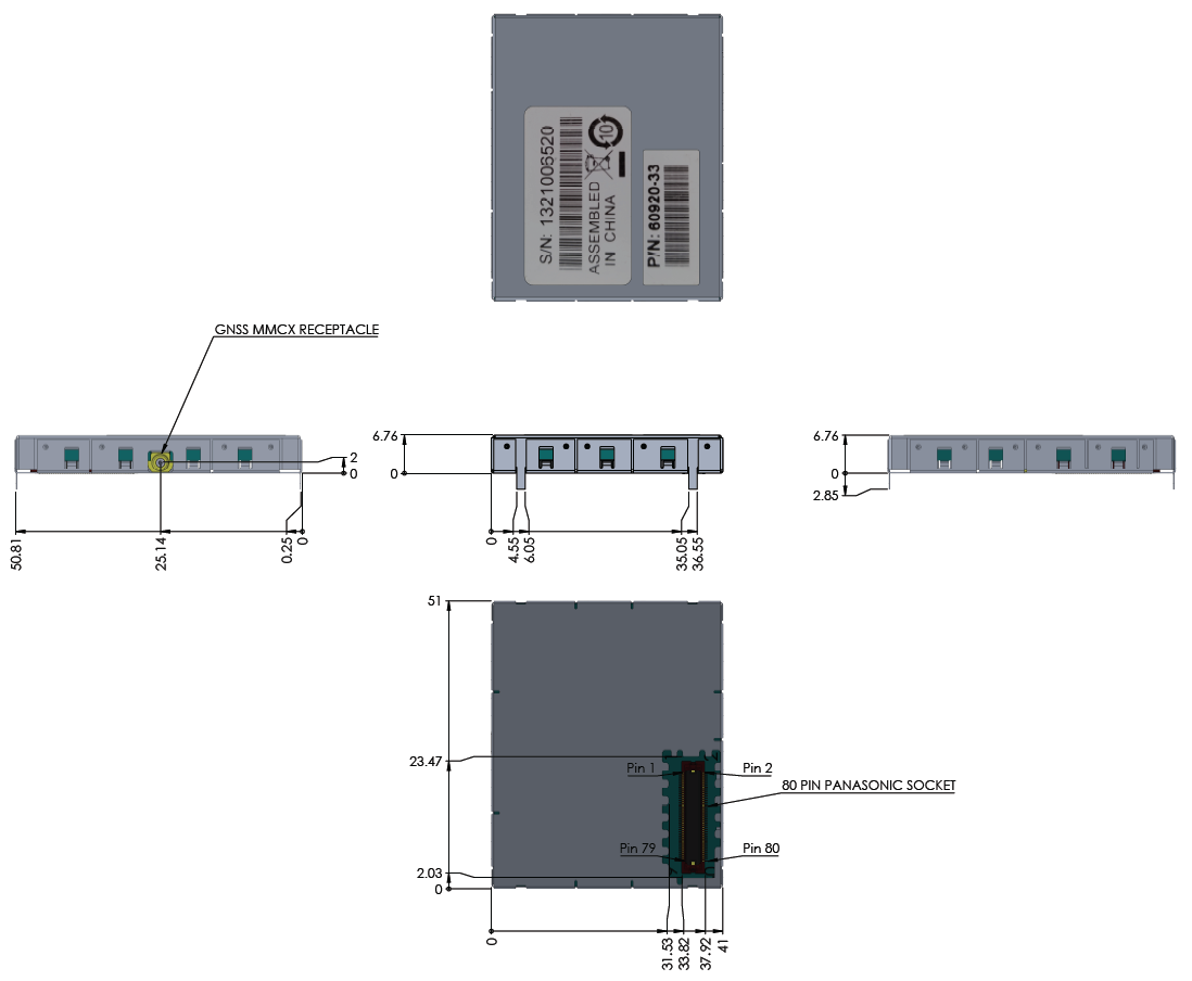
BD940
Below is an overview of the key dimensions of the BD940. If you require a 3D CAD model of the module, please send a request to GNSSOEMSupport@trimble.com.
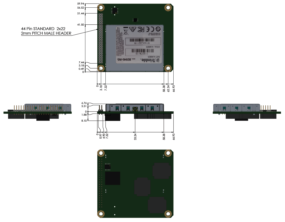
BD940-INS
Below is an overview of the key dimensions of the BD940-INS. If you require a 3D CAD model of the module, please send a request to GNSSOEMSupport@trimble.com.
BD940-INS Center of Navigation
When measuring-up an Inertial Navigation System, the measurements to the IMU are made to the Center of Navigation shown below:
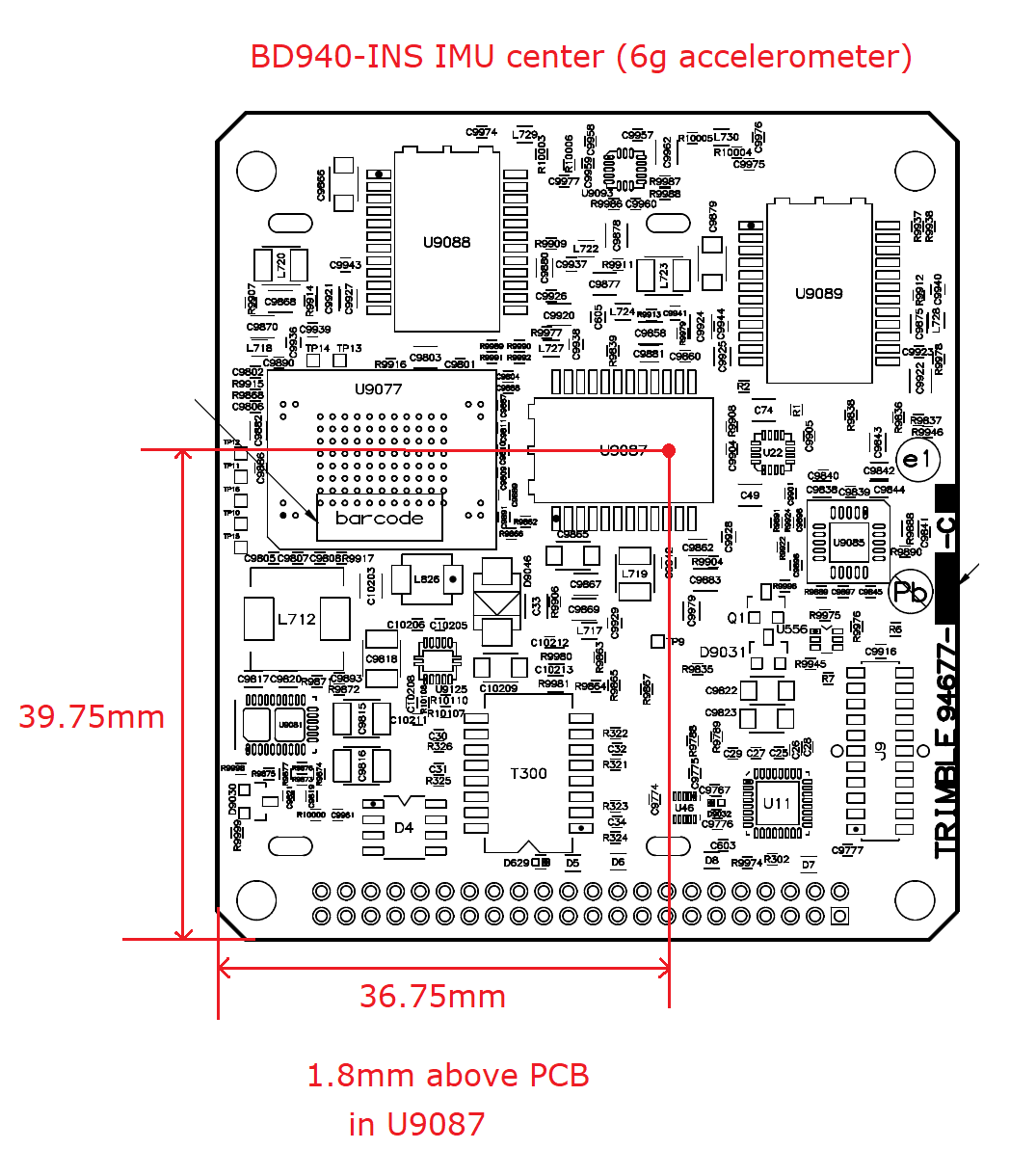
The X-axis points toward the 44-pin connector, and the Z-axis pointing away from the 44-pin connector (the dimensions and axes below are shown from the center of the board):