Drawings
Applicable receivers: BX992
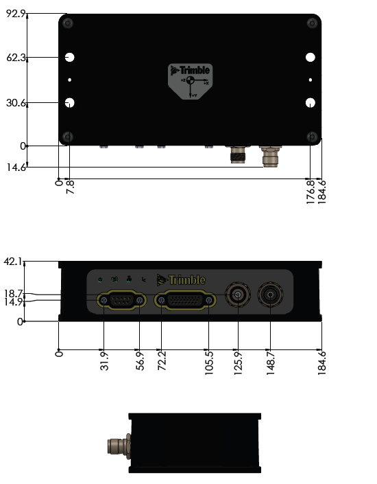
Key dimensions of the receiver enclosure are shown here. If you require a 3D CAD model of the module, please send a request to GNSSOEMSupport@trimble.com.
Main dimensions
Center of navigation
When measuring up an Inertial Navigation System, the measurements to the IMU are made to the Center of Navigation (CoN) as shown:
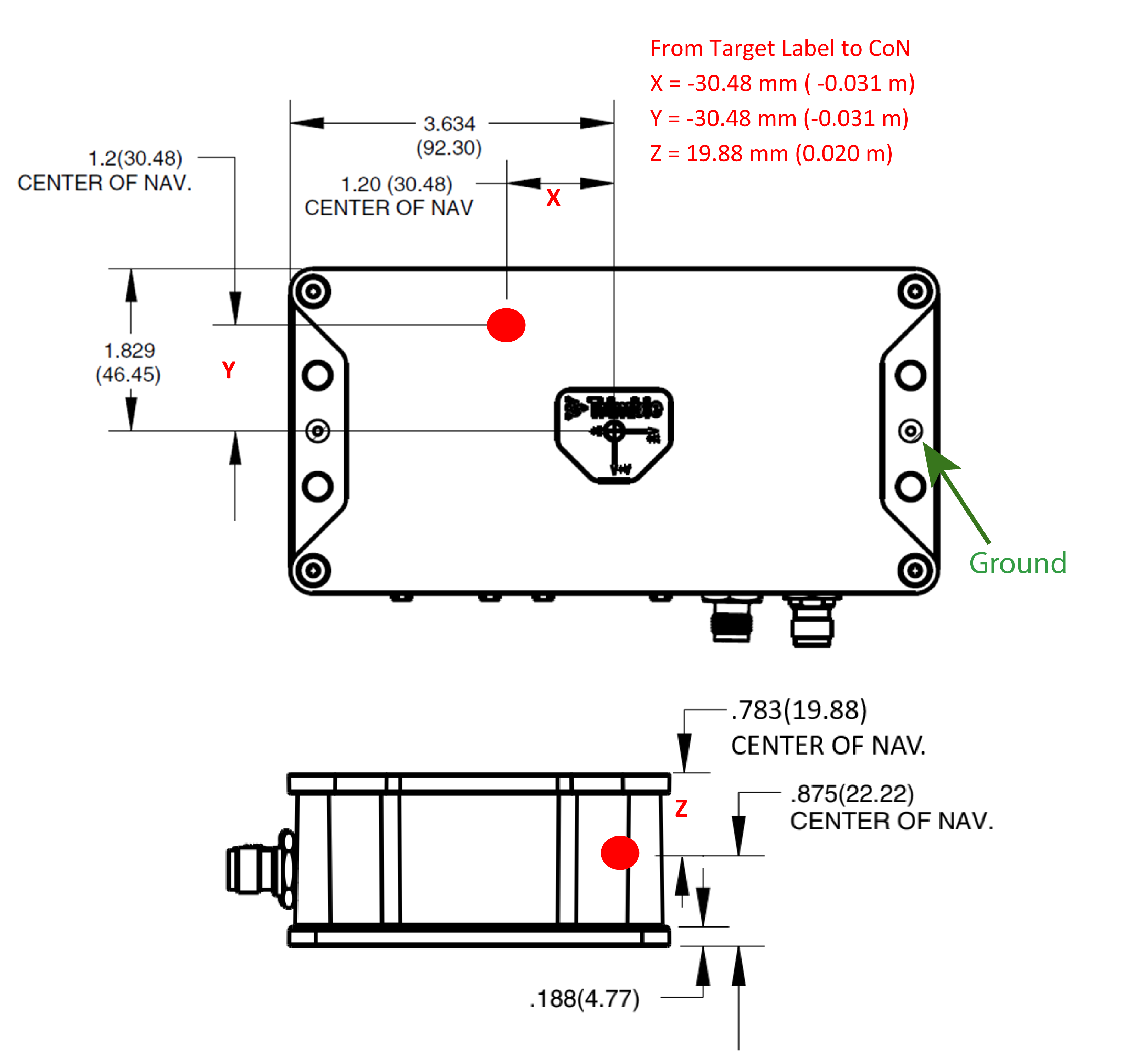
The axes are indicated on the label, with the Y-axis pointing through the connector side of the housing, and the Z-axis pointing through the bottom of the housing.
Use a Pan Head 4-40 × ¼ Inch Coarse Thread Machine Fastener to tie the ground wire from the receiver enclosure. Use "Red" Lock Tight.
