Drawings
Applicable receivers: AX940 | AX940i
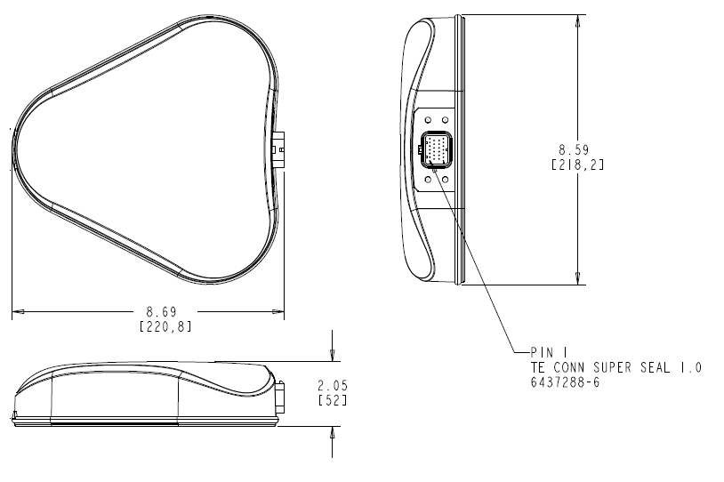
Below is an overview of the key dimensions of the smart antenna. If you require a 3D CAD model of the module, please send a request to GNSSOEMSupport@trimble.com.
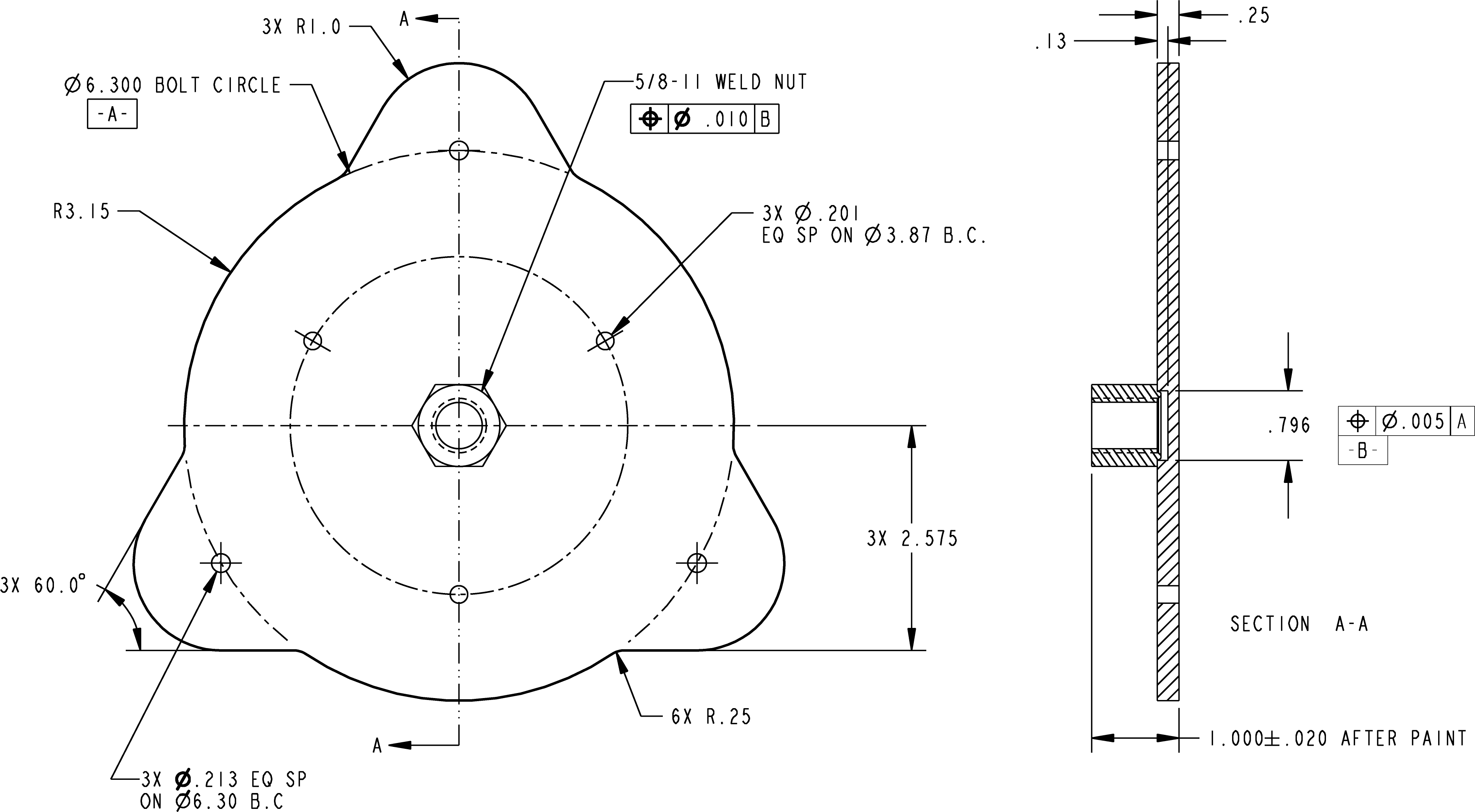
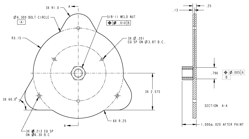
The smart antenna can be mounted to a main mounting plate using M5 bolts with a max torque rating of 5.65 Nm. The mounting hole pattern is shown below:
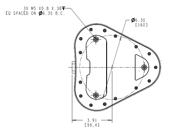
CAUTION – Mounting bolts should not travel into the base to a depth of more than 0.38 inches (9.6 mm).
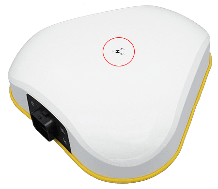
INS reference location and center of navigation
Since the AX940i is a smart antenna, the center of navigation (for the IMU axis center) is always in the same relative position to the antenna phase center. The only setup parameters required to establish its location is the Vehicle to Receiver Mounting Angles field in the INS Configuration screen.
The reference location will be set at the antenna phase center unless otherwise specified in the INS Configuration screen. The antenna phase center is located at the axis label on the radome (on the surface of the radome). If a Reference to Primary GNSS Lever Arm is specified, it should be measured from the reference location to this point.
Optional accessory
P/N 119273 mounting plate, 5/8"-11, AX940/AX940i, black for 5/8” mast mounting