Configuring the receiver using the web interface or TRIMCOMM commands
Applicable receivers: All receivers
This topic describes how to configure the receivers using the web interface and/or the Binary TRIMCOMM™ commands.
It comprises the following sections:
Useful links:
-
For a description of the web user interface, see Menus.
-
For the API documentation, see API documentation - Introduction to the receiver interface protocol.
Base station setup
When setting up the base station, Trimble recommends the following steps:
-
Reset the unit to use the default application file. Select Receiver / Reset:
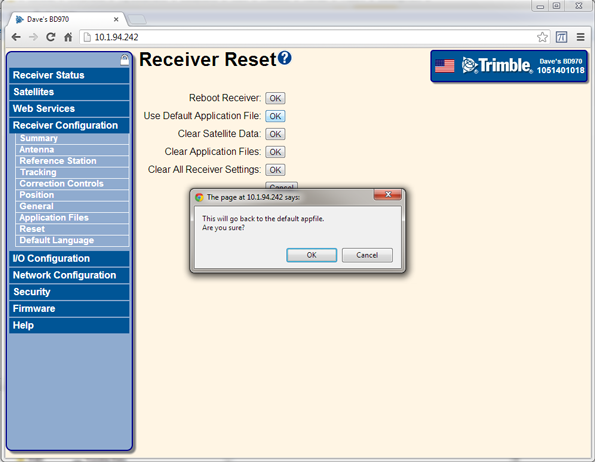
Once the receiver has reset, the web page will update to show a message that the reset is complete.
-
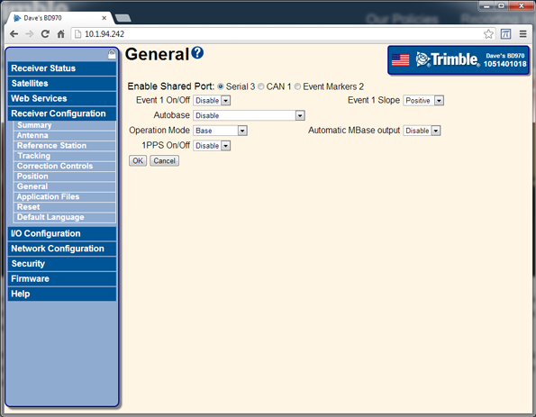
Select Receiver Configuration / General. Set Operation Mode to Base:
-
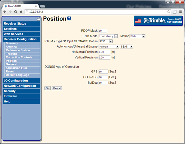
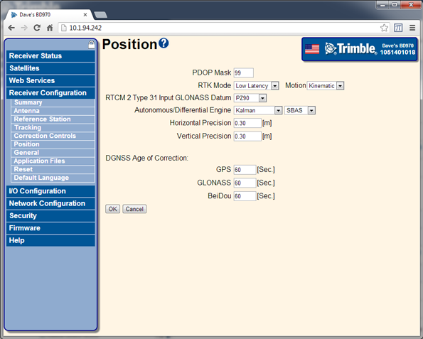
Select Receiver Configuration / Position. Set Receiver Motion to Static:
The 64h command to reset the receiver to defaults and put the unit into static mode is:
02 00 64 0A 00 00 00 03 00 01 01 0A 01 01 7F 03
Where:
RECORD BYTES: 0A 01 01
Decode as:
RECORD TYPE: 10 (0Ah (10) Static Kinematic)
RECORD LENGTH: 1
Static/Kinematic Mode: 1 (Static)NOTE – The highlighted bit is set to 01 only in this command (since it resets the unit to defaults). In the following steps this bit is set to 00 since a reset at that point would reset all of the settings that have already been configured.
-
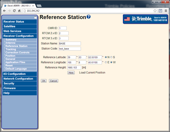
Select Receiver Configuration / Reference Station. Set the CMR and RTCM ID values, station names and codes, and the reference position of the base station:
The 64h command to set these base parameters is:
02 00 64 62 00 00 00 03 00 01 00 03 59 00 00 42 41 53 45 20 20 20 20 3F E6 48 80 57 7F A2 1F BF FD 5A 5D DD 52 DF 68 40 9A 04 9C AC 08 31 27 00 02 01 40 41 42 41 53 45 20 20 20 20 20 20 20 20 20 20 20 20 20 20 20 20 42 74 65 73 74 5F 62 61 73 65 20 20 20 20 20 20 20 44 41 4E 4D 43 34 20 20 20 20 40 00 03 89 03
Where:
RECORD BYTES: 03 59 00 00 42 41 53 45 20 20 20 20 3F E6 48 80 57 7F A2 1F BF FD 5A 5D DD 52 DF 68 40 9A 04 9C AC 08 31 27 00 02 01 40 41 42 41 53 45 20 20 20 20 20 20 20 20 20 20 20 20 20 20 20 20 42 74 65 73 74 5F 62 61 73 65 20 20 20 20 20 20 20 44 41 4E 4D 43 34 20 20 20 20 40 00 03
Decode as:
RECORD TYPE: 3 (03h Reference Node)
RECORD LENGTH: 89
Flag (Reserved - set to 0x00): 0x00 (0)
Node Index (Reserved - set to 0x00): 0x00 (0)
Name: BASE
Reference Latitude (radians): 0.696350260635
Reference Longitude (radians): -1.834562172457
Reference Altitude (meters): 1665.1530
RTCM v2.x Station ID: 2
CMR Station ID: 1
Frame Character (@): @
Station ID indicator: A
Station Point ID: BASE
Feature Code indicator: B
Feature Code: test_base
Epoch Rate indicator: D
Base quality indicator: A
Base point class indicator: N
Tracking indicator: 01001101
Antenna Type: 184
Flag (Reserved - set to 0x20): 0x20 (32)
Protocol Indicator (set to 0x20): 0x20 (32)
Flag (Reserved - set to 0x20): 0x20 (32)
Flag (Reserved - set to 0x20): 0x20 (32)
Frame Character (@): @
RTCM v3.x Station ID: 3 -
Select Receiver Configuration / Antenna. Set the antenna type, antenna height, and the measurement method:
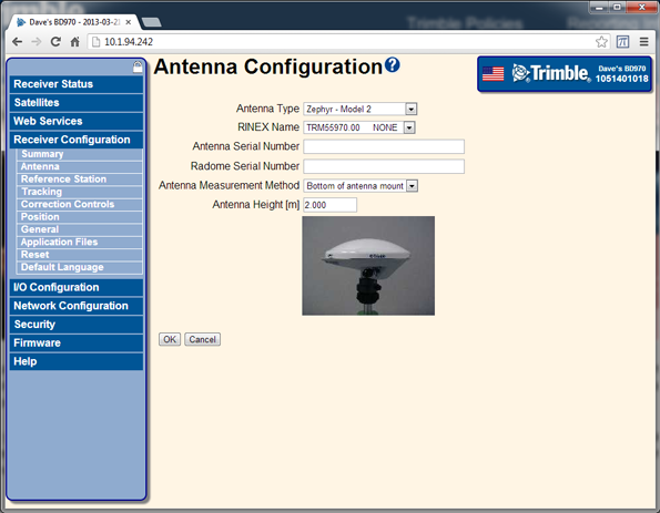
The 64h command to set these base parameters is:
02 00 64 15 00 00 00 03 00 01 00 08 0C 40 00 AC A5 7A 00 00 00 00 B8 00 00 54 03
Where:
RECORD BYTES: 08 0C 40 00 AC A5 7A 00 00 00 00 B8 00 00
Decode as:
RECORD TYPE: 8 (08h (8) Antenna)
RECORD LENGTH: 12
Antenna Height (meters): 2.0843
Antenna Type: 184
(Reserved - set to 0x00): 0
(Reserved - set to 0x00): 0NOTE – In this example, because the bottom of antenna mount (the ARP) was selected, the antenna height accounts for the distance between the antenna phase center (APC) and the ARP. However, the output messages are always given for the position of the APC.
-
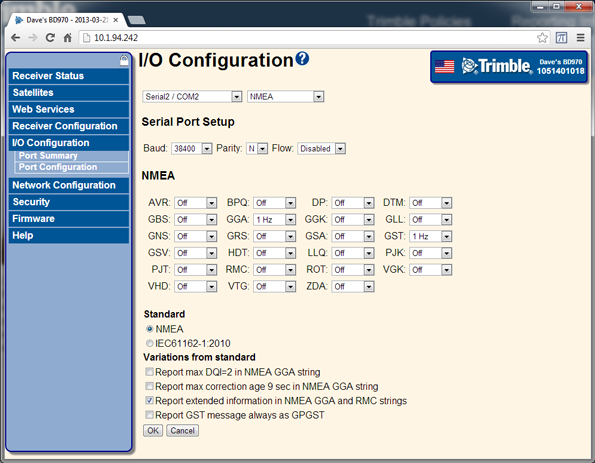
Select I/O Configuration / Port Configuration. Configure the CMR or RTCM correction output. You can configure bandwidth limiting if required:
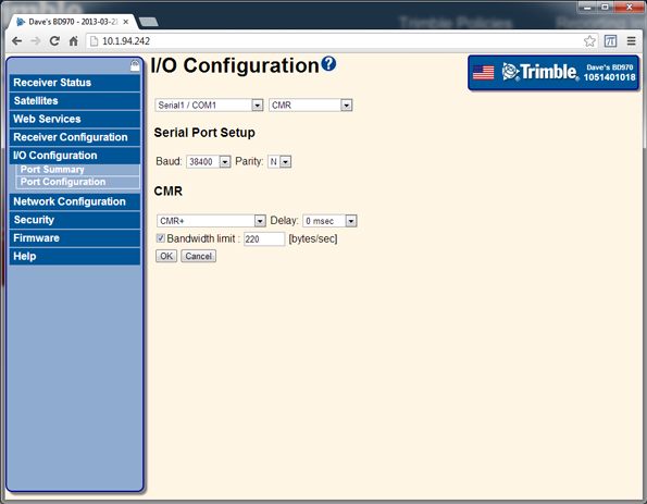
The 64h command to set these base parameters is:
02 00 64 1B 00 00 00 03 00 01 00 02 04 01 05 00 00 07 0C 02 00 03 00 00 00 00 DC 00 00 00 00 83 03
Where:
RECORD BYTES: 02 04 01 05 00 00
Decode as:
RECORD TYPE: 2 (02h (2) Serial Port Baud Format)
RECORD LENGTH: 4
PORT INDEX (zero based): 1 (Serial port 2)
BAUD RATE: 5 (38.4K baud (default))
PARITY: 0 (No Parity)
FLOW CONTROL: 0 (None)Where:
RECORD BYTES: 07 0C 02 00 03 00 00 00 00 DC 00 00 00 00
Decode as:
RECORD TYPE: 7 (07h (7) Output Message)
RECORD LENGTH: 12
OUTPUT MESSAGE TYPE: 2 (CMR Output)
PORT INDEX (zero based): 0 (Serial port 1)
FREQUENCY: 3 (1 Hz)
OFFSET: 0
CMR Flag 1: 0 (CMR+)
CMR Flag 2: 0x00
BANDWIDTH LIMIT: 220
EXTRA BYTE1: 0x00
EXTRA BYTE2: 0x00
EXTRA BYTE3: 0x00
EXTRA BYTE4: 0x00 -
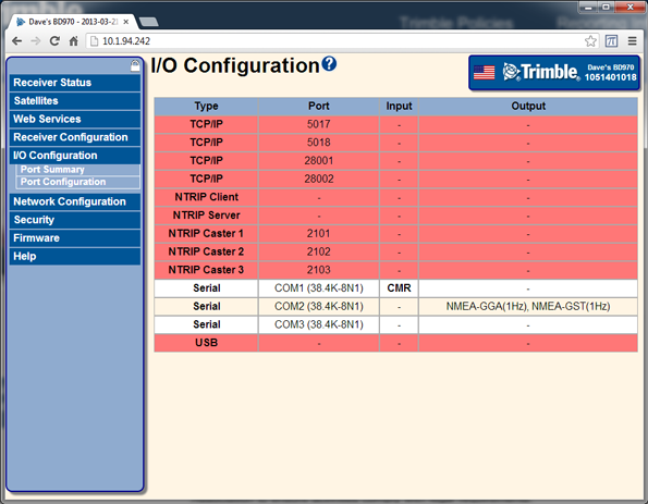
Select I/O Configuration / Port Summary. Verify that the CMR outputs are configured:

-
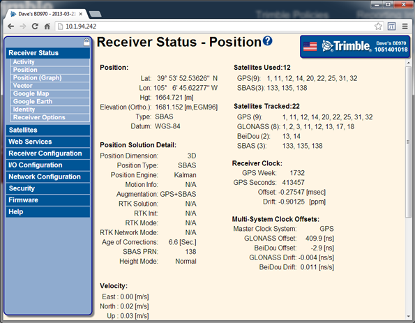
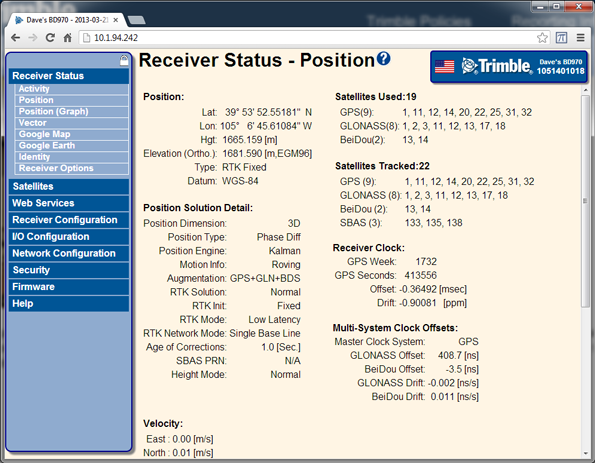
Select Receiver Status / Position. Verify that the base station is tracking satellites and positioning:
Rover setup
When setting up a rover, Trimble recommends the following steps:
-
Reset the unit to use the default application file. Select Receiver / Reset:
Once the receiver has reset, the web page will update to show a message that the reset is complete.
-
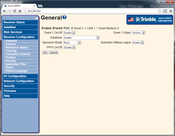
Select Receiver Configuration / General. Set Operation Mode to Rover:
-
Select Receiver Configuration / Position. Set RTK Motion to Kinematic:

The 64h command to reset the receiver to defaults and put the unit into a kinematic mode is:
02 00 64 0A 00 00 00 03 00 01 01 0A 01 00 7E 03
Where:
RECORD BYTES: 0A 01 00
Decode as:
RECORD TYPE: 10 (0Ah (10) Static Kinematic)
RECORD LENGTH: 1
Static/Kinematic Mode: 0 (Kinematic)NOTE – The highlighted bit is set to 01 only in this command (since it resets the unit to defaults). In the following steps this bit is set to 00 since a reset at that point would reset all of the settings that have already been configured.
-
Select Receiver Configuration / Antenna. Set the antenna type, antenna height, and the measurement method:

The 64h command to set these base parameters is:
02 00 64 15 00 00 00 03 00 01 00 08 0C 3F B5 94 AF 40 00 00 00 00 B8 00 00 C0 03
Where:
RECORD BYTES: 3F B5 94 AF 40 00 00 00 00 B8 00 00
Decode as:
RECORD TYPE: 8 (08h (8) Antenna)
RECORD LENGTH: 12
Antenna Height (meters): 0.0843
Antenna Type: 184
(Reserved - set to 0x00): 0
(Reserved - set to 0x00): 0NOTE – In this example, because the bottom of antenna mount (the ARP) was selected, the antenna height accounts for the distance between the antenna phase center (APC) and the ARP. However, the output messages are always given for the position of the APC.
-
Select I/O Configuration / Port Configuration. Configure any output messages:
The 64h command to set these base parameters is:
02 00 64 19 00 00 00 03 00 01 00 02 04 01 05 00 00 07 04 06 01 03 00 07 04 0D 01 03 00 BE 03
Where:
RECORD BYTES: 02 04 01 05 00 00
Decode as:
RECORD TYPE: 2 (02h (2) Serial Port Baud Format)
RECORD LENGTH: 4
PORT INDEX (zero based): 1 (Serial port 2)
BAUD RATE: 5 (38.4K baud (default))
PARITY: 0 (No Parity)
FLOW CONTROL: 0 (None)Where:
RECORD BYTES: 07 04 06 01 03 00
Decode as:
RECORD TYPE: 7 (07h (7) Output Message)
RECORD LENGTH: 4
OUTPUT MESSAGE TYPE: 6 (NMEA_GGA)
PORT INDEX (zero based): 1 (Serial port 2)
FREQUENCY: 3 (1 Hz)
OFFSET: 0Where:
RECORD BYTES: 07 04 0D 01 03 00
Decode as:
RECORD TYPE: 7 (07h (7) Output Message)
RECORD LENGTH: 4
OUTPUT MESSAGE TYPE: 13 (NMEA_GST)
PORT INDEX (zero based): 1 (Serial port 2)
FREQUENCY: 3 (1 Hz)
OFFSET: 0 -
Select I/O Configuration / Port Summary. Verify that the CMR corrections are inputs (if the text is bold, the corrections are being used in the position solution) and verify the output messages:
-
Select Receiver Status / Position. Verify that the rover is tracking satellites and positioning using the input corrections from the base station:
Moving base setup
When setting up a moving base, Trimble recommends the following steps:
-
Reset the unit to use the default application file. Select Receiver / Reset:
-
Select Receiver Configuration / General. Set Operation Mode to Moving Base:

-
Select Receiver Configuration / Position. Set Receiver Motion to Kinematic and RTK Mode to Synchronous:
The 64h command to reset the receiver to defaults and put the unit into a kinematic mode is:
02 00 64 14 00 00 00 03 00 01 01 0A 01 00 01 08 0A 02 63 00 00 00 00 00 00 03
Where:
RECORD BYTES: 0A 01 00
Decode as:
RECORD TYPE: 10 (0Ah (10) Static Kinematic)
RECORD LENGTH: 1
Static/Kinematic Mode: 0 (Kinematic)Where:
RECORD BYTES: 01 08 0A 02 63 00 00 00 00 00
Decode as:
RECORD TYPE: 1 (01h (1) General Controls)
RECORD LENGTH: 9
Elevation Mask: 10
Meas Rate (OBSOLETE): 2 (10Hz)
PDOP Mask: 99
Frequency Source (RESERVED - set to 0x00): 0
Position Source (OBSOLETE - set to 0x00): 0
RTK POSITIONING MODE: 0 (Synchronous positioning)
POSITIONING SOLUTION SELECTION: 0 (Use best available solution)
RESERVED - set to 0x00: 0NOTE – The highlighted bit is set to 01 only in this command (since it resets the unit to defaults). In the following steps this bit is set to 00 since a reset at that point would reset all of the settings that have already been configured.
-
Select Receiver Configuration / Antenna. Set the antenna type, antenna height, and the measurement method:
The 64h command to set these base parameters is:
02 00 64 15 00 00 00 03 00 01 00 08 0C 3F B5 94 AF 40 00 00 00 00 B8 00 00 C0 03
Where:
RECORD BYTES: 3F B5 94 AF 40 00 00 00 00 B8 00 00
Decode as:
RECORD TYPE: 8 (08h (8) Antenna)
RECORD LENGTH: 12
Antenna Height (meters): 0.0843
Antenna Type: 184
(Reserved - set to 0x00): 0
(Reserved - set to 0x00): 0NOTE – In this example, because the bottom of antenna mount (the ARP) was selected, the antenna height accounts for the distance between the antenna phase center (APC) and the ARP. However, the output messages are always given for the position of the APC.
-
Select I/O Configuration / Port Configuration. Configure the Moving Base CMR output:

The 64h command to set these base parameters is:
02 00 64 1B 00 00 00 03 00 01 00 02 04 02 05 00 00 07 0C 02 02 0D 00 01 00 00 00 00 00 00 00 B5 03
Where:
RECORD BYTES: 02 04 02 05 00 00
Decode as:
RECORD TYPE: 2 (02h (2) Serial Port Baud Format)
RECORD LENGTH: 4
PORT INDEX (zero based): 2 (Serial port 3)
BAUD RATE: 5 (38.4K baud (default))
PARITY: 0 (No Parity (10-bit format))
FLOW CONTROL: 0 (None)Where:
RECORD BYTES: 07 0C 02 02 0D 00 01 00 00 00 00 00 00 00
Decode as:
RECORD TYPE: 7 (07h (7) Output Message)
RECORD LENGTH: 12
OUTPUT MESSAGE TYPE: 2 (CMR Output)
PORT INDEX (zero based): 2 (Serial port 3)
FREQUENCY: 13 (20 Hz)
OFFSET: 0
CMR Flag 1: 1 (High speed CMR (5, 10, or 20 Hz))
CMR Flag 2: 00000000
BANDWIDTH LIMIT: 0
EXTRA BYTE1: 0x00 (0)
EXTRA BYTE2: 0x00 (0)
EXTRA BYTE3: 0x00 (0)
EXTRA BYTE4: 0x00 (0) -
Configure any output messages:
The 64h command to set these base parameters is:
02 00 64 19 00 00 00 03 00 01 00 02 04 01 05 00 00 07 04 06 01 03 00 07 04 0D 01 03 00 BE 03
Where:
RECORD BYTES: 02 04 01 05 00 00
Decode as:
RECORD TYPE: 2 (02h (2) Serial Port Baud Format)
RECORD LENGTH: 4
PORT INDEX (zero based): 1 (Serial port 2)
BAUD RATE: 5 (38.4K baud (default))
PARITY: 0 (No Parity)
FLOW CONTROL: 0 (None)Where:
RECORD BYTES: 07 04 06 01 03 00
Decode as:
RECORD TYPE: 7 (07h (7) Output Message)
RECORD LENGTH: 4
OUTPUT MESSAGE TYPE: 6 (NMEA_GGA)
PORT INDEX (zero based): 1 (Serial port 2)
FREQUENCY: 3 (1 Hz)
OFFSET: 0Where:
RECORD BYTES: 07 04 0D 01 03 00
Decode as:
RECORD TYPE: 7 (07h (7) Output Message)
RECORD LENGTH: 4
OUTPUT MESSAGE TYPE: 13 (NMEA_GST)
PORT INDEX (zero based): 1 (Serial port 2)
FREQUENCY: 3 (1 Hz)
OFFSET: 0 -
Select I/O Configuration / Port Summary. Verify that the CMR corrections are inputs (if the text is bold, the corrections are being used in the position solution) and verify the output messages:

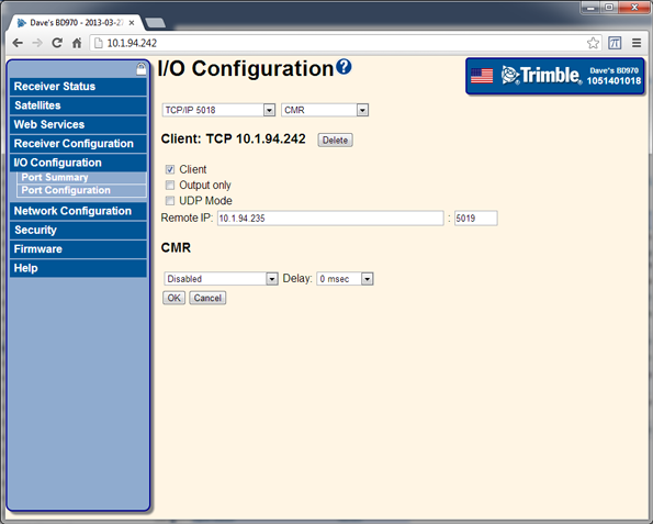
Setting up input/output on ethernet ports
Configure the TCP or UDP ports to send data the same way as with the serial ports. When configuring the TCP or UDP ports to receive data, they must be put into a client mode and the source/server must be specified. Select I/O Configuration / Port Configuration:
Using the AEh command to get the ethernet configuration
When working with the receivers using TRIMCOMM commands, the IP address of the receiver can be found by sending the AEh ETHERNET CFG subtype 00h command, for example:
02 00 AE 01 00 AF 03
The receiver responds with the AEh ETHERNET CFG subtype 01h response, like this:
02 28 AE 16 01 00 0A 01 5E F2 FF FF FE 00 0A 01 5F FF 0A 01 5E 01 0A 01 50 18 8A 03
Which decodes as:
DHCP ACTIVE: 0
IP Address byte 1: 10
IP Address byte 2: 1
IP Address byte 3: 94
IP Address byte 4: 242
NETMASK byte 1: 255
NETMASK byte 2: 255
NETMASK byte 3: 254
NETMASK byte 4: 0
BROADCAST ADDRESS byte 1: 10
BROADCAST ADDRESS byte 2: 1
BROADCAST ADDRESS byte 3: 95
BROADCAST ADDRESS byte 4: 255
GATEWAY byte 1: 10
GATEWAY byte 2: 1
GATEWAY byte 3: 94
GATEWAY byte 4: 1
DNS SERVER ADDRESS byte 1: 10
DNS SERVER ADDRESS byte 2: 1
DNS SERVER ADDRESS byte 3: 80
DNS SERVER ADDRESS byte 4: 24
The AEh ETHERNET CFG subtype 02h command can be used to set these parameters.
Using the AEh command to get the virtual IP ports
The receiver uses a “virtual port” for the IP ports which allows a single byte to identify the port. To find the available virtual ports for the TCP and UDP ports on the IP stack, send the AEh ETHERNET CFG subtype 0Ch command, for example:
02 00 AE 01 0C BB 03
The receiver responds with the AEh ETHERNET CFG subtype 0Dh response, like this:
02 E8 AE 08 0D 15 1E 04 15 16 17 18 3C 03
Which decodes as:
FIRST VIRTUAL PORT (1-based): 0x15 (21)
LAST VIRTUAL PORT (1-based): 0x1E (30)
No. ACTIVE VPORTS: 4
ACTIVE VPORTS (1-based): 0x15 (21)
ACTIVE VPORTS (1-based): 0x16 (22)
ACTIVE VPORTS (1-based): 0x17 (23)
ACTIVE VPORTS (1-based): 0x18 (24)
These are the port addresses that must be used in the 64h commands for sending output messages from a TCP or UDP port.
Using the AEh command to get details on, or set, a virtual IP port
To find details about a specific port, send the AEh ETHERNET CFG subtype 0Eh command, for example (on port 16h):
02 00 AE 02 0E 16 D4 03
The receiver responds with the AEh ETHERNET CFG subtype 0Fh response, like this:
02 E8 AE 1F 0F 16 01 13 9A 00 3C 00 00 01 13 9B 00 00 00 00 00 00 00 0B 31 30 2E 31 2E 39 34 2E 32 33 35 A1 03
Which decodes as:
VIRTUAL PORT (1-based): 0x16 (22)
ACTIVE: 1
IP Port: 5018
Mode: 0
UDP TIMEOUT: 60
OUTPUT ONLY: 0
AUTHENTICATE: 0
INITIATE CONNECTION: 1
REMOTE IP PORT: 5019
AUTHENTICATION KEY:
REMOTE IP ADDR LENGTH: 11
REMOTE IP ADDRESS: 10.1.94.235
In this case you can see that the port is configured in a client mode, connected to 10.1.94.235. The AEh ETHERNET CFG subtype 10h command can be used to set these parameters.
