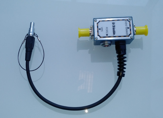
Event Marker/1PPS cable
The following cable is available:
P/N 36451-02: Cable ASSY EVENT MARKER/1PPS
Used for power input to port 4, event marker in and 1PPS output.

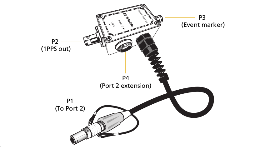
The event marker/1PPS cable provides a breakout box with two BNC (female) connectors for 1PPS input and event marker output.
Connect a device that accepts 1PPS output pulses to the BNC connector labeled 1PPS on the breakout box. Connect a device that outputs event marker pulses to the receiver, such as a photogrammetric camera, to the BNC connector labeled Event Marker on the breakout box.

In addition, the breakout box includes a Lemo 7-pin connector to extend serial communications and/or power on port 4. Because the BNC connectors are used to service the event marker and 1PPS features, pins 4 (1PPS) and 5 (Event Marker) are inactive on the Lemo connector.
For port 4 pinouts, see Lemo connectors (port 3 and 4).
The following pinouts are for the event marker/1PPS cable. The event marker/1PPS cable is used only with the receiver connector Port 4 ( for event marker output).
|
Lemo port 4 |
|
Direction |
P2: BNC-F connector 1PPS |
P3: BNC-F connector (event marker) |
P4: Lemo 7-pin port 4 extensions |
|
|
|---|---|---|---|---|---|---|---|
|
Pin |
Usage |
|
Pin |
Pin |
Pin |
Usage |
|
|
1 |
RS232 GND |
ß |
|
|
1 |
RS232 GND |
|
|
2 |
GND |
à |
GND (shield) |
GND (shield) |
2 |
GND |
|
|
3 |
Data out |
ß |
|
|
3 |
Data out |
|
|
4 |
1PPS |
ß |
Center pin |
|
4 |
No connection |
|
|
5 |
Event marker |
ßà |
|
Center pin |
5 |
No connection |
|
|
6 |
Pwr In + |
à |
|
|
6 |
Pwr In + |
|
|
7 |
Data In |
ß |
|
|
7 |
Data In |
|