Multiplexed port control commands
Applicable receivers: BD970, BD982, BD990, BD992, BD992-INS, BD9250
The BD970, BD982, BD990, BD992, and BD992-INS receiver modules have a single multiplex port that can be controlled with the Multiplexed port control record. The BD940 and BD940-INS multiplexed port is controlled with the General controls record. The BD9250 receiver module has three multiplexed ports and requires the following commands to configure each multiplex port. These commands will also work on BD970, BD982, BD990, BD992, and BD992-INS receiver modules, but not the BD940 or BD940-INS receiver modules.
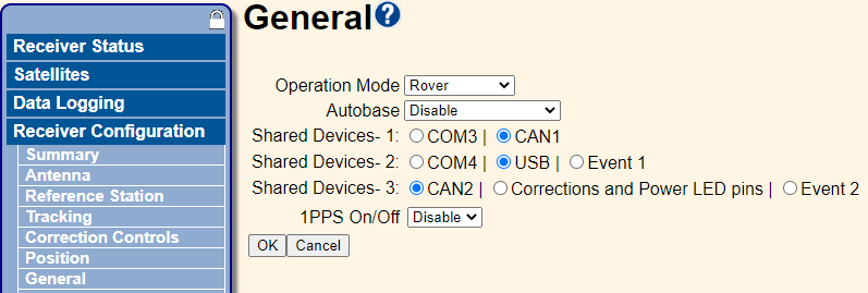
For the BD9250 receiver module, the multiplex switch numbering corresponds to the shared device numbering seen in the web interface. See General.
Query current multiplex state
The following table defines the record to query the current multiplex state
|
Byte |
Item |
Type |
Value |
Notes |
|---|---|---|---|---|
|
0 |
STX |
1 (Char) |
02h |
Start transmission |
|
1 |
STATUS |
1 (Char) |
Receiver status indicator |
|
|
2 |
PACKET TYPE |
1 (Char) |
3Eh |
Command/Response packet 3Eh |
|
3 |
LENGTH |
1 (Char) |
Data byte count |
|
|
4 |
MULTIPLEX SWITCH |
1 (Char) |
01h, 02h, 03h |
Multiplex switches:
|
|
5 |
SUBTYPE |
1 (Char) |
FEh |
Subtype FEh is valid for the Multiplex port |
|
6 |
CHECKSUM |
1 (Char) |
Checksum value |
|
|
7 |
ETX |
1 (Char) |
03h |
End transmission |
Query response to current multiplex state
The following table defines the record to query response for the current multiplex state:
|
Byte |
Item |
Type |
Value |
Notes |
|---|---|---|---|---|
|
0 |
STX |
1 (Char) |
02h |
Start transmission |
|
1 |
STATUS |
1 (Char) |
Receiver status indicator |
|
|
2 |
PACKET TYPE |
1 (Char) |
3Fh |
Command/Response packet 3Fh |
|
3 |
LENGTH |
1 (Char) |
Data byte count |
|
|
4 |
MULTIPLEX SWITCH |
1 (Char) |
|
|
|
5 |
MULTIPLEX CODE |
10 (Char) |
00h |
|
|
6 |
CHECKSUM |
1 (Char) |
Checksum value |
|
|
7 |
ETX |
1 (Char) |
03h |
End transmission |
Set multiplex state
The following table defines the record to set the current multiplex state. When successful, an ACK (o6h) will be returned, NAK (15h) indicates a failure or misconfiguration.
|
Byte |
Item |
Type |
Value |
Notes |
|---|---|---|---|---|
|
0 |
STX |
1 (Char) |
02h |
Start transmission |
|
1 |
STATUS |
1 (Char) |
Receiver status indicator |
|
|
2 |
PACKET TYPE |
1 (Char) |
48h |
Command/Response packet 48h |
|
3 |
LENGTH |
1 (Char) |
Data byte count |
|
|
4 |
MULTIPLEX SWITCH |
1 (Char) |
01h, 02h, 03h |
Multiplex switches:
|
|
5 |
MULTIPLEX CODE |
1 (Char) |
Subtype FEh is valid for the Multiplex port |
|
|
6 |
CHECKSUM |
1 (Char) |
Checksum value |
|
|
7 |
ETX |
1 (Char) |
03h |
End transmission |
Selected Multiplex Code byte values
The following table provides byte values for the information in the multiplexed port control record. For the BD9250 receiver module, the multiplexed switch that this is available on is also indicated.
|
Byte value |
BD970, BD982, BD990, BD992, and BD992-INS |
BD9250 |
|---|---|---|
|
0 |
None |
None |
|
1 |
CAN1 |
CAN2 (MUX3) |
|
2 |
COM3 |
RESERVED |
|
3 |
Event 2 |
RESERVED |
|
4 |
|
RESERVED |
|
5 |
|
COM3 (MUX1) |
|
6 |
|
CAN1 (MUX1) |
|
7 |
|
RESERVED |
|
8 |
|
COM4 (MUX2) |
|
9 |
|
USB (MUX2) |
|
10 |
|
Event 1 (MUX2) |
|
11 |
|
LED Output (MUX3) |
|
12 |
|
Event 2 (MUX3) |
