Interface board evaluation kit
Applicable receivers: BD970
An evaluation kit is available for testing the receiver. It includes an I/O board that gives access to:
-
Power input connector
-
Power ON/OFF switch
-
Three serial ports through DB9 connectors
-
Ethernet through an RJ45 connector
NOTE – There are separate ethernet jacks for the BD960/BD982 and BD970 boards.
-
USB port through USB Type B receptacle
-
CAN port through a DB9 connector
-
Two event input pins
-
1PPS output on BNC connector
-
CAN / Serial port 3 switch
NOTE – To switch between serial port 3 and CAN, you must configure the receiver using the web interface or binary commands. If you do not set an option bit to make CAN the default, the receiver defaults to serial.
-
Three LEDs to indicate satellite tracking, receipt of corrections, and power
The following figure shows a typical I/O board setup:
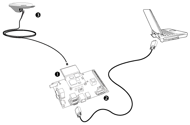
1 BD970 receiver
2 I/O board
3 Zephyr antenna
The computer connection provides a means to set up and configure the receiver.
Current or prospective customers may obtain schematic drawings of the evaluation I/O board by contacting GNSSOEMSupport@trimble.com.
