USB
Applicable receivers: BD940 | BD940-INS | BD982 | BD990 | BD992 | BD992-INS
The CPU of the receiver has an integrated PHY that supports both USB 2.0 Device and Host configuration at low-speed, full-speed, and high-speed. In Host mode, the receiver supplies 5 V to a USB device, such as a memory stick. In Device mode, the receiver behaves like an external storage device to a computer.
USB OTG reference design
To be OTG-compliant, the connector must be MICRO AB. An OTG-compliant cable has A and B ends. When the B-side of the cable is inserted, the ID pin is not connected (floating) and the receiver enters Device mode through a pull-up resistor. The A-side of the cable connects the ID pin to ground, which enables Host mode on the receiver.
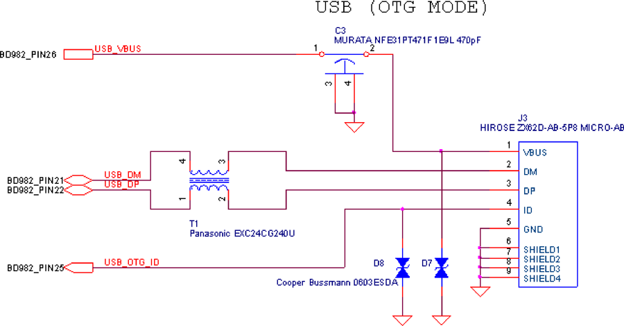
To reduce EMI, place a USB 2.0 compliant common mode choke on the data lines. To ensure best EMI performance, locate the choke near the USB MICRO AB connector. Trimble recommends that you use an L-C-L type EMI filter for the output power.
For product robustness and protection, place ESD protection diodes on both the USB_VBUS and USB_OTG_ID lines. The receiver has internal high-speed ESD protection on the USB data lines.
To ensure best USB high-speed performance, carefully consider PCB routing and placement practices:
-
Place components so the trace length is minimized.
-
Do not have stubs on data lines more than 0.200".
-
Route data lines differentially but as parallel as possible.
-
Data lines must be controlled to 90 Ohms differential impedance, and 45 Ohms single-ended impedance.
-
Route over continuous reference plane (either ground or power).
For more detailed information, refer to the Intel High Speed USB Platform Design Guidelines.
USB host-only reference design
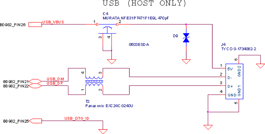
For USB host-only support, a type-A connector is required. Since the receiver dos not support dynamic role switching, the ID pin should be grounded on the receiver. In Host mode, the receiver supplies nominal 5 V output at 500 mA to the USB device.
USB device-only reference design
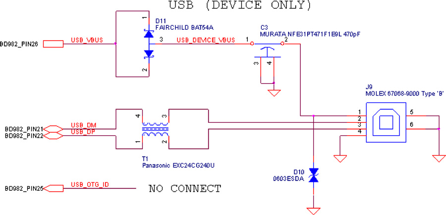
For device-only operation, the USB_OTG_ID pin is left floating. For reference, the receiver has an internal 10 K Ohm pull-up to 3.3 V. In this mode, the USB_DEVICE_VBUS is used only by receiver to detect if host power is connected.
BD940 evaluation board
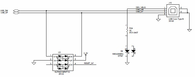
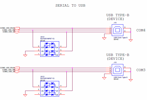
The BD940 evaluation board has two Serial – USB ports. The ports are named COM3 and COM4. The USB connectors are Type-B connectors. Below is the schematic for the two Serial – USB communication ports.
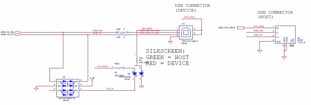
The BD940 evaluation board is also equipped to handle both USB Device and Host. There are two USB ports available on the evaluation board that provide this functionality. Below is the schematic that details the connections involved with both USB modes.
BD940-INS evaluation board
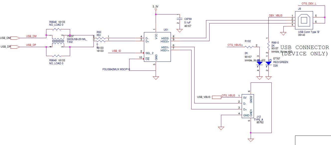
The following is the schematic for the USB Type-B (device only) connector on the BD940-INS evaluation board:
BD99x evaluation board
The BD99X evaluation board has one USB device port. The following is the schematic for this communication port: