USB
Applicable receivers:
The CPU of the receiver has an integrated PHY that supports both USB 2.0 Device and Host configuration at full-speed and high-speed. The receiver determines if it should operate as a host or device through the USB_ID pin. Leaving floating or pulled-up through a 10-k-ohm resistor to 3.3V will cause the receiver to operate as a USB device. Driving USB_ID to 0V (GND) will force the receiver to operate.
In Host mode, the integrator is required to provide 5 V on VBUS on the USB connector. In host mode, the receiver will be able to datalog to a USB flash drive.
In Device mode, the receiver operates as a USB composite device that behaves like an external storage device to a computer, a virtual serial (COM) port, and a UPnP network device. The user is able to access datalogging files through the external storage interface. This is similar to connecting a memory card into a PC’s USB port. The virtual serial (COM) port allows the user to communicate to the receiver like any of the other 3 native serial ports. Each receiver will create a unique virtual serial port. The UPnP interface allows the user to access the receiver’s webpage. The default IP address is 192.168.144.1. This is configurable. There may be issues if connected to multiple receivers without changing the default configuration
USB-C connector
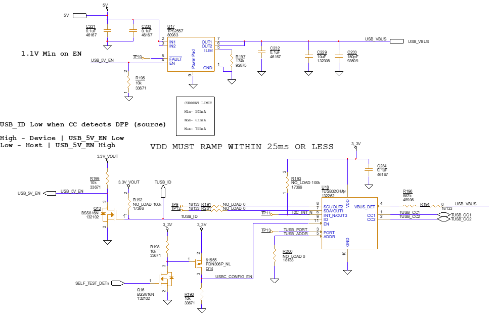
The reference design below is what is used on the 105679-E IO board. It supports a USB-C connector and both host and device mode
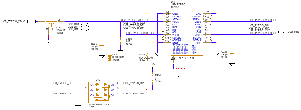
USB-C controller and USB-VBUS switch
USB-C controller reads the USB-C connector’s CC pins and determines the appropriate USB_ID pin setting. TI’s TUSB320IRWBR is used for this role
USB_VBUS is set using an external 5V supply (not included in the reference design) and TI’s TPS2557 load switch. USB_ID enables and disables this switch.
If only host or device mode is used, the integrator can use standard USB-A or USB-B connected and pre-set the USB_ID pin the appropriate setting. Additionally, legacy mini-USB or Micro-USB connectors that directly drive USB_ID can be used
To reduce EMI, place a USB 2.0 compliant common mode choke on the data lines. To ensure best EMI performance, locate the choke near the USB connector. Trimble recommends that you use an L-C-L type EMI filter for the output power.
For product robustness and protection, place ESD protection diodes on both the USB_VBUS and USB_ID lines. The receiver has internal high-speed ESD protection on the USB data lines.
To ensure best USB high-speed performance, carefully consider PCB routing and placement practices:
-
Place components so the trace length is minimized.
-
Do not have stubs on data lines more than 0.200".
-
Route data lines differentially but as parallel as possible.
-
Data lines must be controlled to 90 Ohms differential impedance, and 45 Ohms single-ended impedance.
-
Route over continuous reference plane (either ground or power).
For more detailed information, refer to the Intel High Speed USB Platform Design Guidelines.
