LED control lines
Applicable receivers: BD9250 | BD940 | BD940-INS | BD970 | BD990 | BD982 | BD992 | BD992-INS
For information about LED patterns, see LED operations.
|
Item |
Description |
|---|---|
|
Driving LEDs |
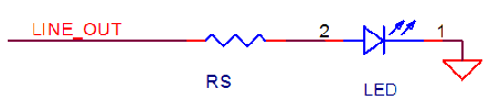
The outputs are 3.3 V TTL level with a maximum source/sink current of 4 mA. An external series resistor must be used to limit the current. The value of the series resistor in Ohms is determined by: (3.3-Vf)/(If) > Rs > (3.3 V - Vf)/(.004) Rs = Series resistor If = LED forward current, max typical If of the LED should be less than 3 mA Vf = LED forward voltage, max typical Vf of the LED should be less than 2.7 V Most LEDs can be driven directly as shown in the circuit below:
LEDs that do not meet If and Vf specification must be driven with a buffer to ensure proper voltage level and source/sink current. |
|
Power LED |
This active-high line indicates that the unit is powered on. |
|
Satellite LED |
This active-high line indicates that the unit has acquired satellites. A rapid flash indicates that the unit has less than five satellites acquired, while a slow flash indicates greater than five satellites acquired. This line will stay on if the unit is in monitor mode. |
|
RTK Correction |
A slow flash indicates that the unit is receiving corrections. This will also flash when the unit is in monitor mode. |