CAN
Applicable receivers: BD9250 | BD940-INS | BD990 | BD992 | BD992-INS
BD9250
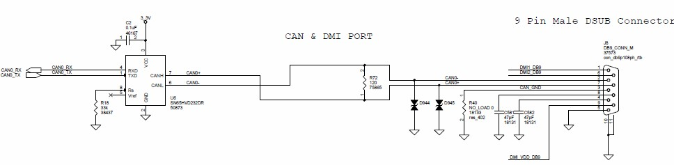
The BD9250 receiver module does not have the capability for CAN. To output CAN messages, the receiver module needs an external CAN transceiver. There are two CAN ports on the main IO connector: CAN1 and CAN2. These CAN ports are at 3.3 V TTL level RX/TX and require a CAN transceiver installed on the I/O board. CAN1 is multiplexed with COM3. CAN2 is multiplexed with Power LED signals and EVENT2.
BD940
The BD940 receiver module does not have the capability for CAN. To output CAN messages, the receiver module needs an external CAN transceiver.
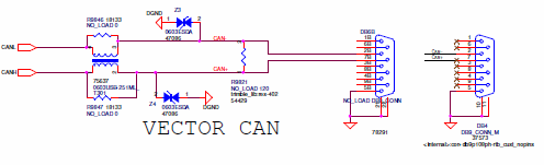
The following figure shows a typical implementation with a 3.3 V CAN transceiver. It also shows a common mode choke as well as ESD protection. A 5 V CAN Transceiver can be used if proper level translation is added.
BD940-INS evaluation board CAN port
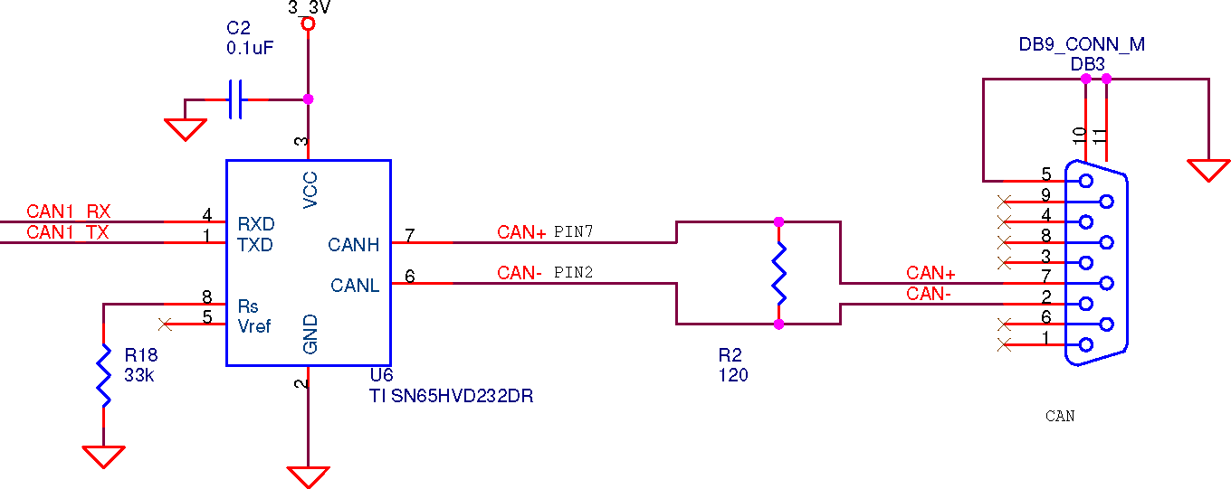
For CAN development using the BD940-INS evaluation board, the provided CAN port is already connected to a CAN transceiver. This port is marked as “CAN” on the board. The connector used is a standard 9-pin DB9 connector.
BD99X evaluation board CAN port
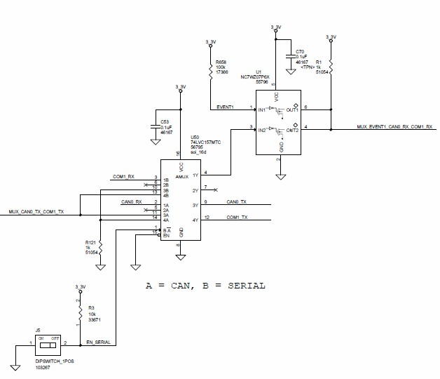
Com 4 is at 0 – 3.3 V TTL and is multiplexed with CAN. The receive line is also multiplexed with Event 1. The integrator must have a receiver configured to use the CAN port in order to use this port as a serial port. The functionality cannot be multiplexed in real time.
For development using the I/O board, this com port is already connected to a CAN transceiver. This is labeled CAN on the I/O board. J5, labeled ‘CAN’ and ‘SERIAL’, must be set to CAN. There shouldn't be anything connected to TP6, labeled Event 1.