Evaluation board layout
Applicable receivers:
Current or prospective customers can obtain schematic drawings of the evaluation I/O board by contacting GNSSOEMSupport@trimble.com.
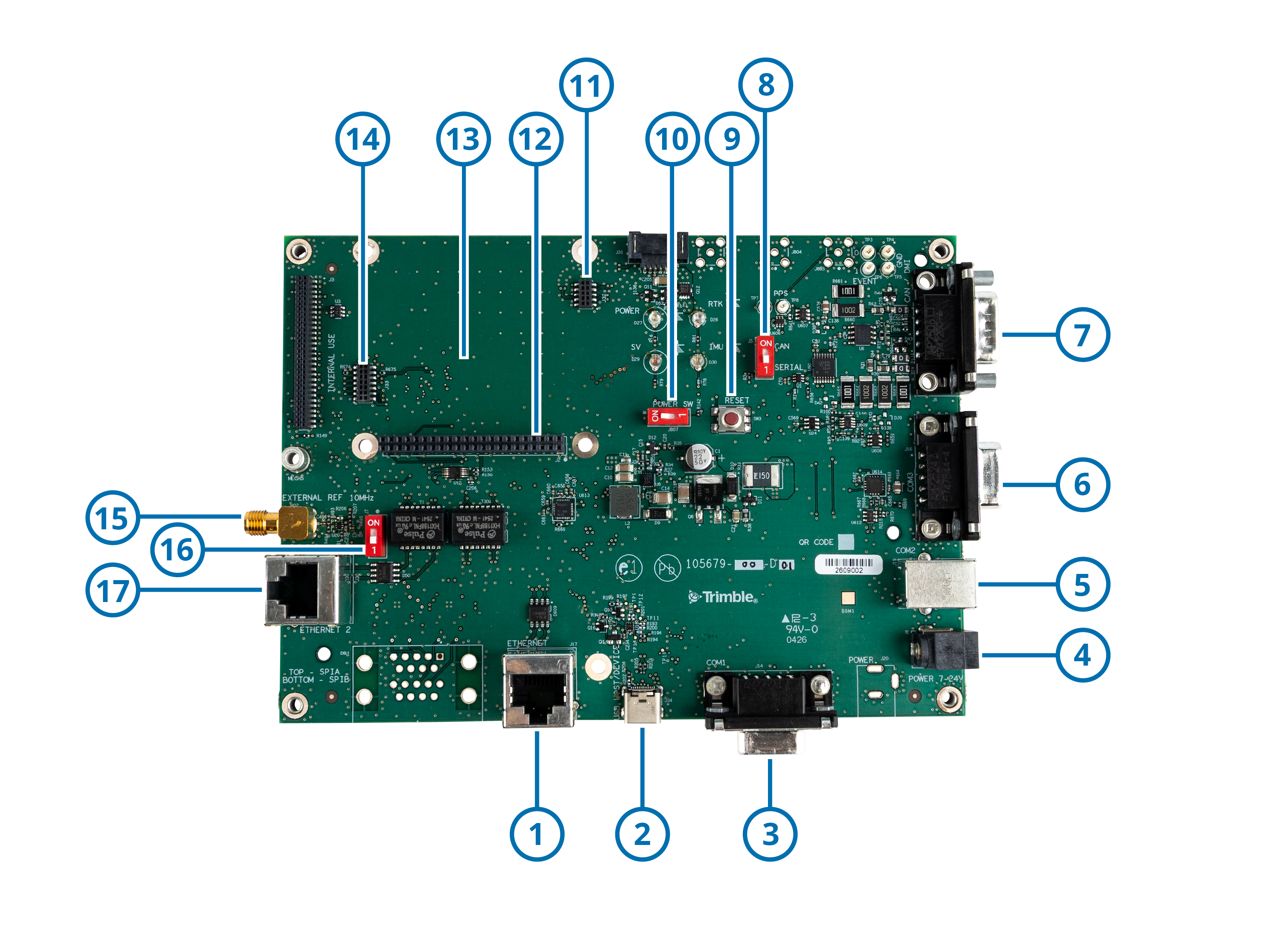
|
1 |
Ethernet |
10 |
Power switch |
|
2 |
Type-C USB port device |
11 |
10-pin SAMTEC (P/N CLP-105-02-L-D-BE-A-K-TR) |
|
3 |
D-Sub9 RS-232 COM 1 |
12 |
44-pin SAMTEC (P/N SQW-122-01-L-D) |
|
4 |
Power input |
13 |
BD109x board location |
|
5 |
Type-B USB VCP COM 2 |
14 |
14-pin SAMTEC (P/N CLP-107-02-L-D-BE-A-K-TR) |
|
6 |
D-Sub9 RS-232 COM 3 |
15 |
External 10 MHz clock SMA connector |
|
7 |
D-Sub9 RS-232 CAN |
16 |
Toggle "ON" external 10 MHz clock |
|
8 |
CAN/RS-232 COM 3 switch |
17 |
Ethernet 2 |
|
9 |
Reset button |
|
|
The functionality to use an external 10 MHz clock (rather than the internal 10 MHz TCXO) requires that this clock is connected to the SMA connector (15) and that switch (16) is toggled “ON”, then the unit should be powered up. If switch (16) is toggled “ON” with no external 10 MHz clock to SMA connector (15), the CPU will not boot because no clock input is present.
