Drawings
Applicable receivers: BX1092i
Key dimensions of the receiver enclosure are shown here. This drawing is also available as a PDF file for download.
If you require a 3D CAD model of the module, please send a request to GNSSOEMSupport@trimble.com.
When measuring up an Inertial Navigation System, the measurements to the IMU are made to the Center of Navigation (CoN) as shown.
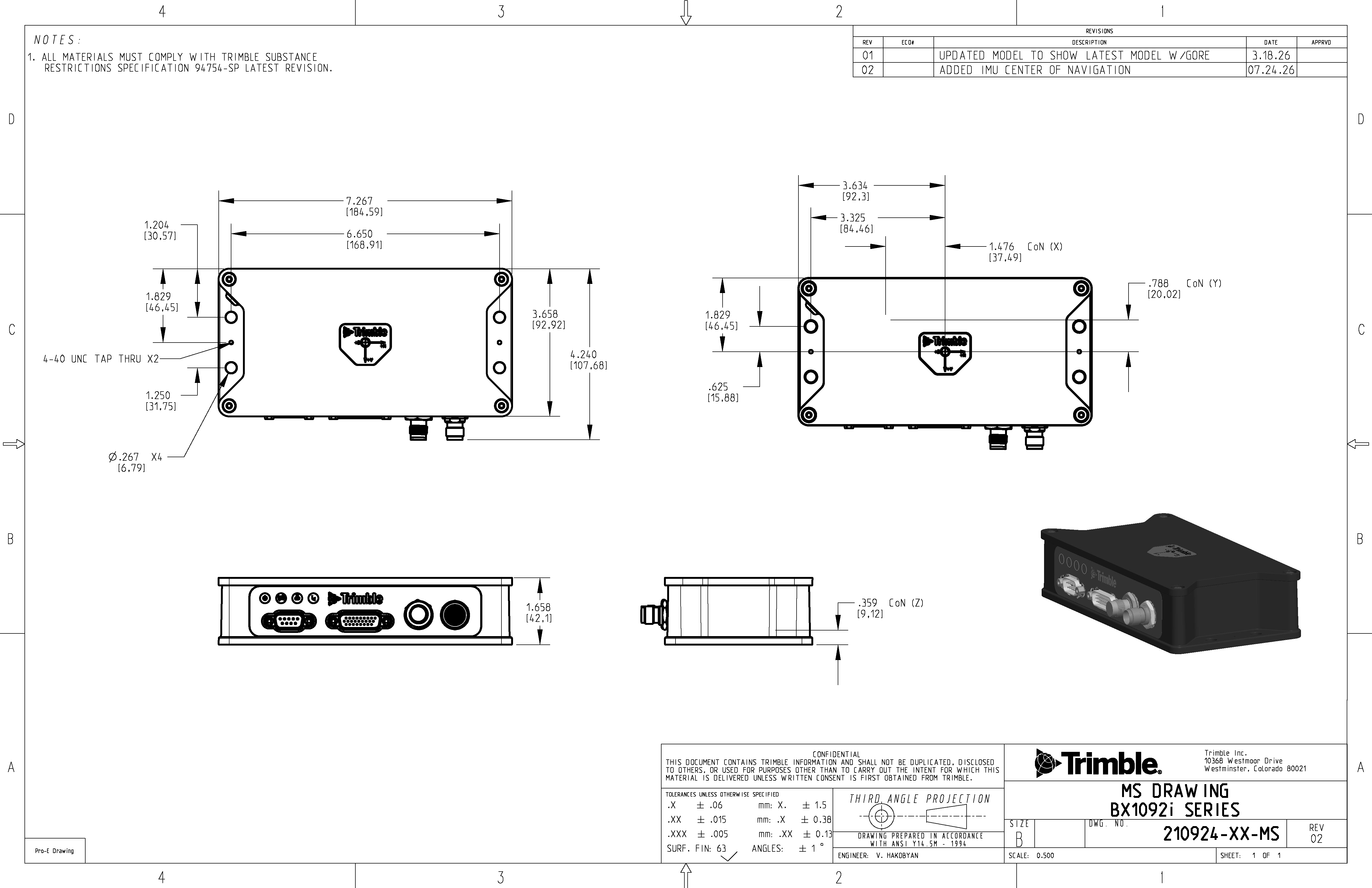
The axes are indicated on the label, with the Y-axis pointing through the connector side of the housing, and the Z-axis pointing through the bottom of the housing.
Use a Pan Head 4-40 × ¼ Inch Coarse Thread Machine Fastener to tie the ground wire from the receiver enclosure. Use "Red" Lock Tight.
